Mechanical Seal
What is a mechanical seal?
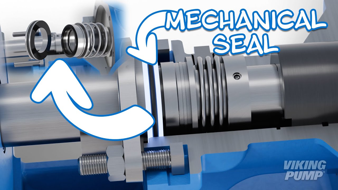
Mechanical seals prevent liquid leakage by creating a hydrodynamic liquid film between two highly finished surfaces. In pumps, the simplest mechanical seals have one rotating surface and one static surface. They come in a variety of types and can be found in different pump technologies e.g., internal gear, external gear, and centrifugal pumps.

How does a mechanical seal work?
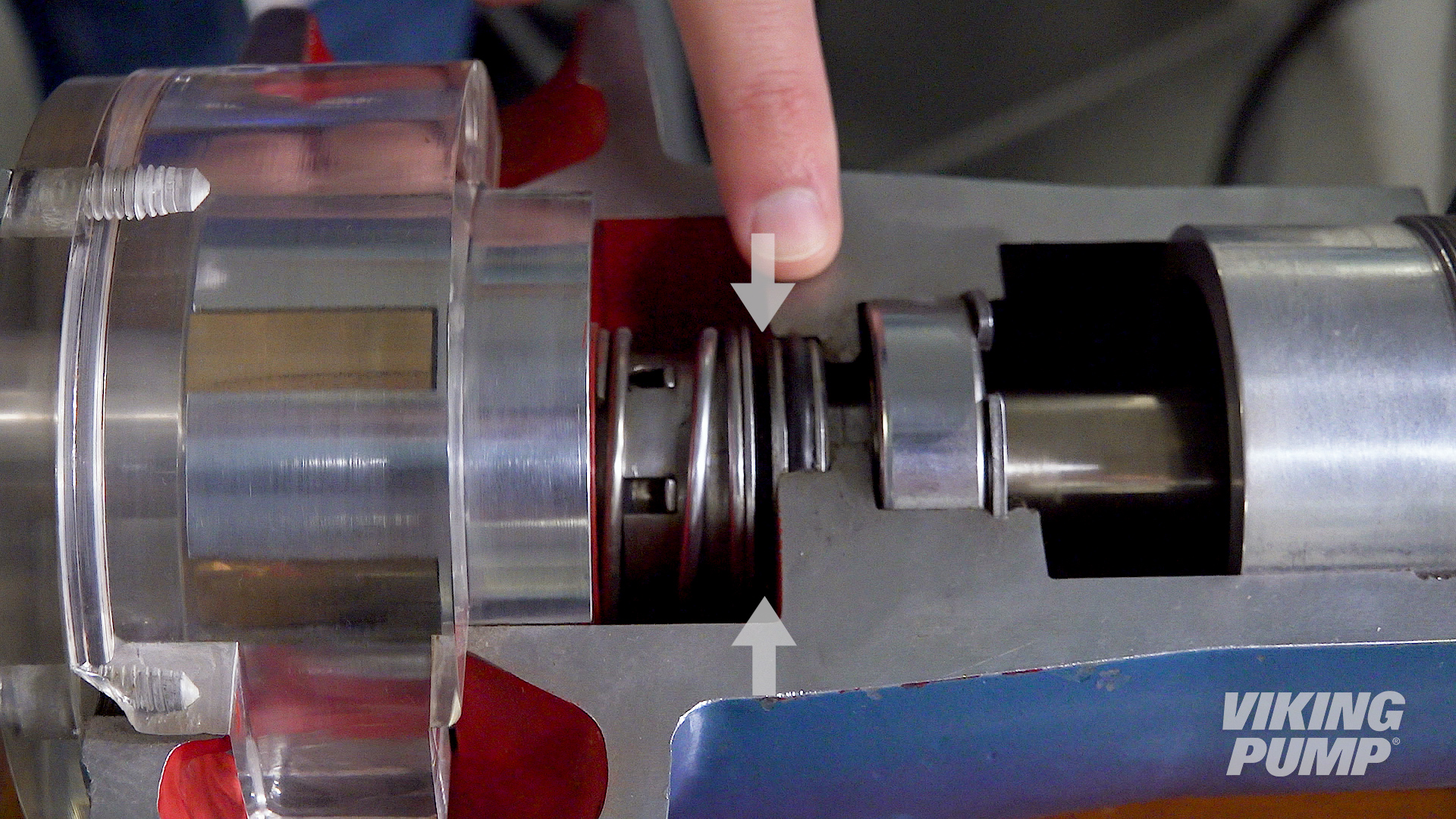
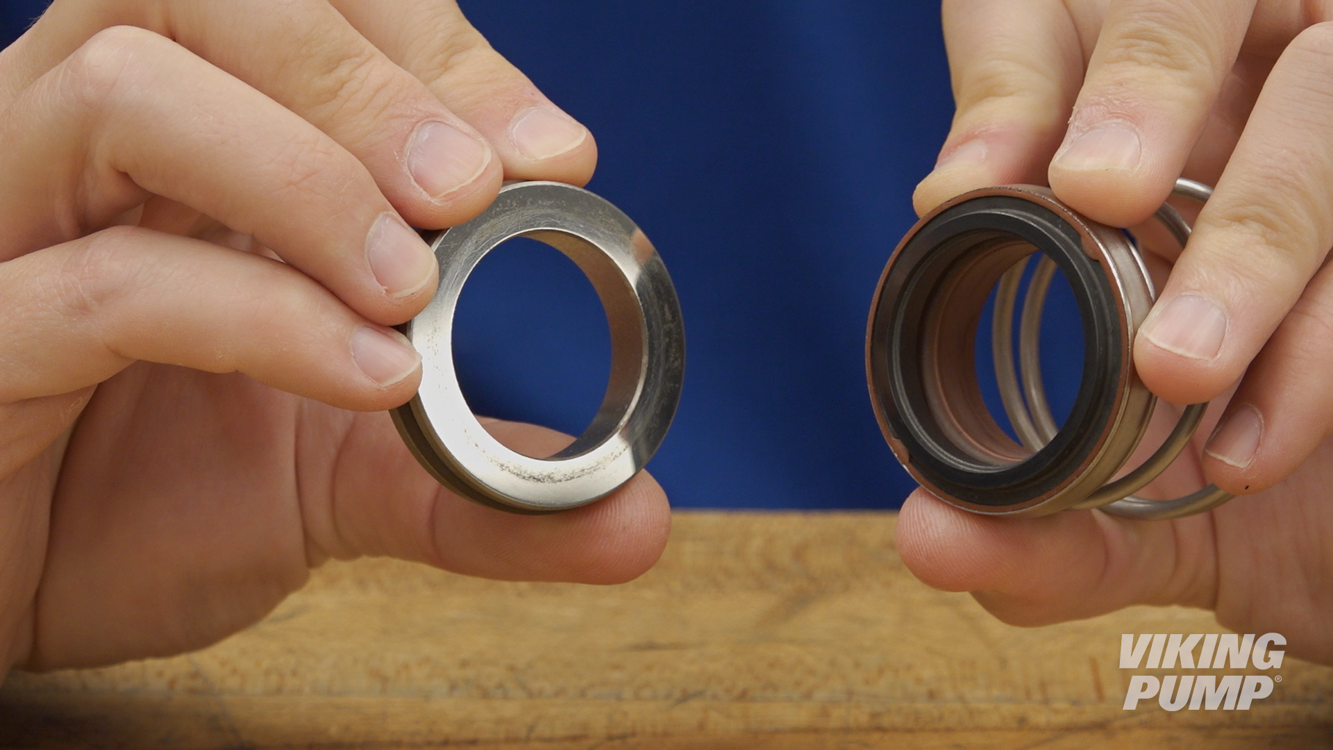
Mechanical seals work by utilizing two separate seal faces. One seal face (static) is typically installed into the pump housing, or bracket, while the other (rotary face) is installed onto the pump shaft. These two seal faces are glossy and highly finished. When liquid is being pumped, process fluid will work it’s way toward the seal faces. When liquid finally enters the space between the seal faces, a hydrodynamic film is created which creates the seal and lubricates the faces. This is the primary seal. A spring helps hold the seal faces together to maintain the primary seal.
Secondary seals are created by o-rings, bellows, or gaskets that prevent leakage past the gland or along the shaft.
What are the different types of mechanical seals?
There are many different seal types and designs when it comes to mechanical seals. Here are a few common examples for those used in Viking pumps:
- Single component seal – made up of a static and rotary seal face and pushed together by a spring. Primary seal is created by a film of process liquid between the two seal faces. Secondary seals are created by o-rings, bellows, or gaskets.
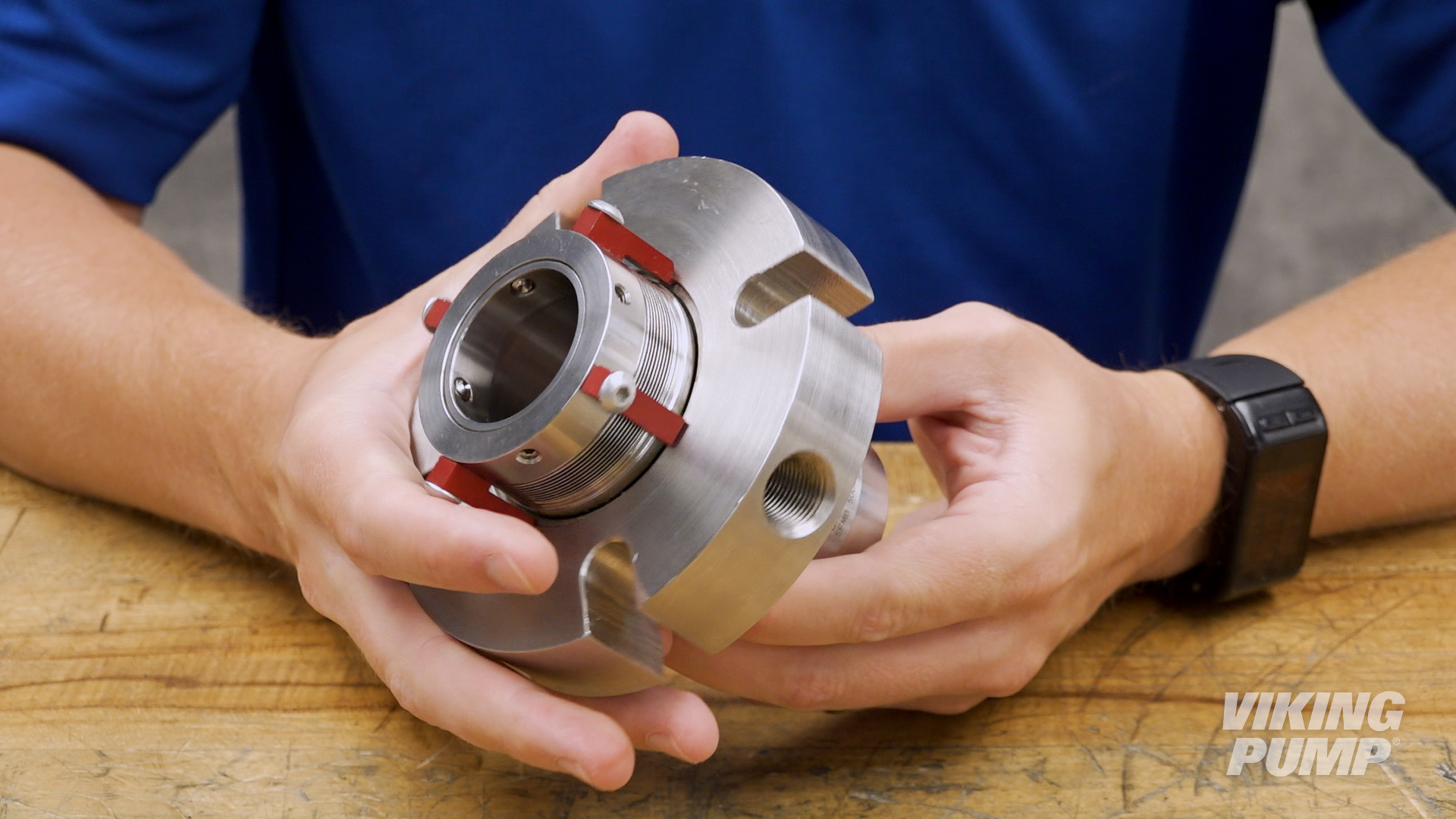
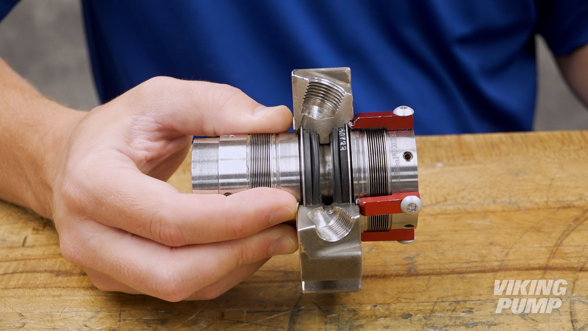
- Cartridge mechanical seal – all of the working parts of the come in a pre-set housing. This makes installation significantly easier.
- Double Mechanical seals – These seals utilize two mechanical seals in a housing. A barrier liquid is applied into the housing between the two seals. This prevents exposure of the process liquid to the environment and it used for toxic, flammable, or difficult to seal liquids.
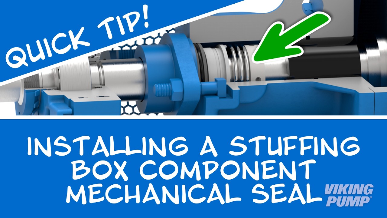
How to install a mechanical Seal
Here are some basic steps for installing a cartridge seal. These steps will vary depending on the type of seal and the pump technology it’s going into, but for this example these steps relate to installing a cartridge mechanical seal into Viking Pump’s 4124A Series™.
| 1. Place the seal installation sleeve into the shaft and lubricate the sleeve and shaft. | 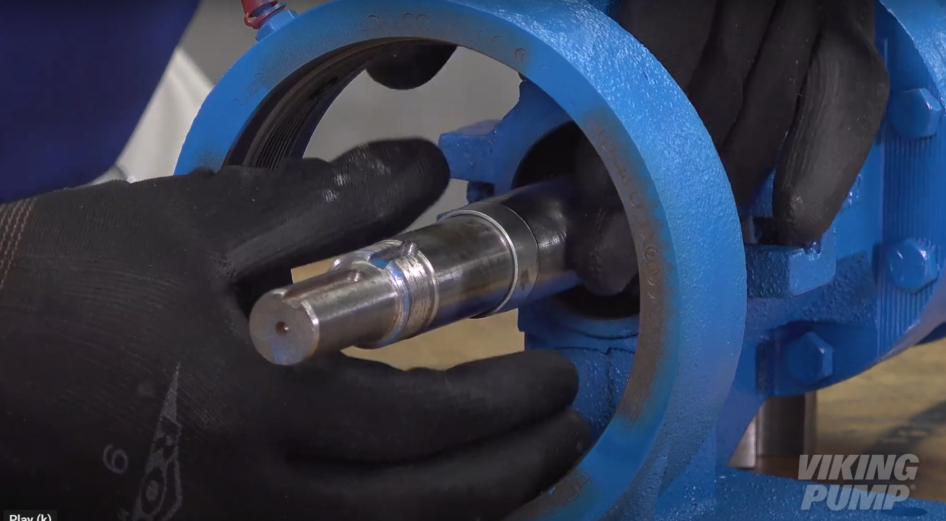 |
| 2. Slide the seal assembly onto the shaft and over the installation sleeve until the assembly contacts the bracket face. | 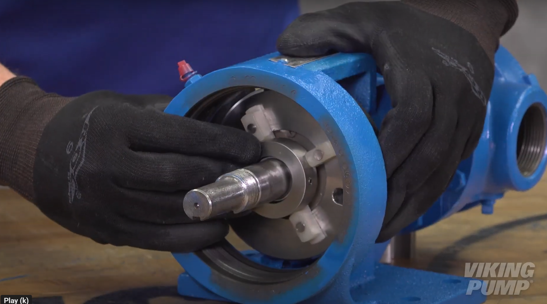 |
| 3. Remove the installation sleeve. | |
| 4. Reassemble the pump and set the end clearance. | |
| 5. Install the gland cap screws. Do not fully tighten at this time. | 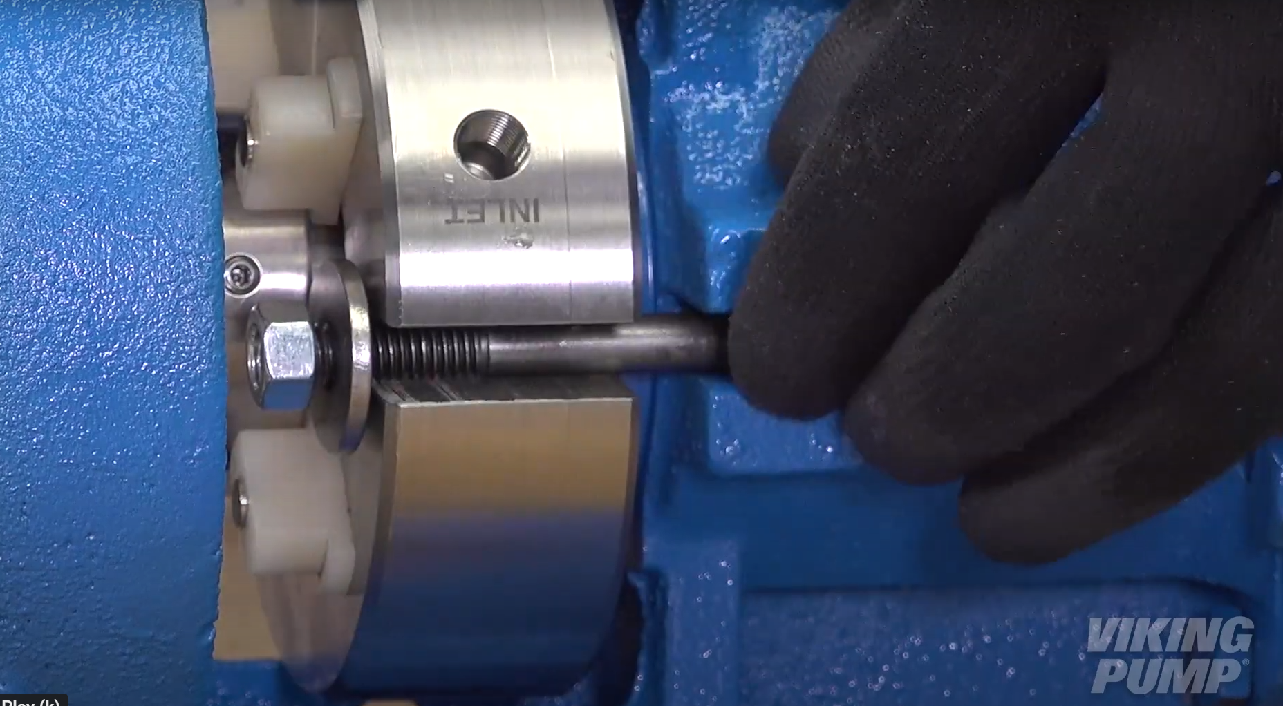 |
| 6. Turn the shaft several times to center the seal. | |
| 7. Tighten the cap screws tight enough to compress the seal gasket. | |
| 8. Evenly tighten the seal sleeve set screws to set the collar to the shaft. | 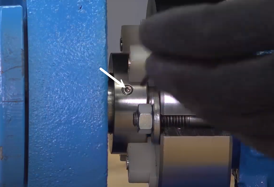 |
| 9. Rotate or remove the seal spacers and check rotation. | 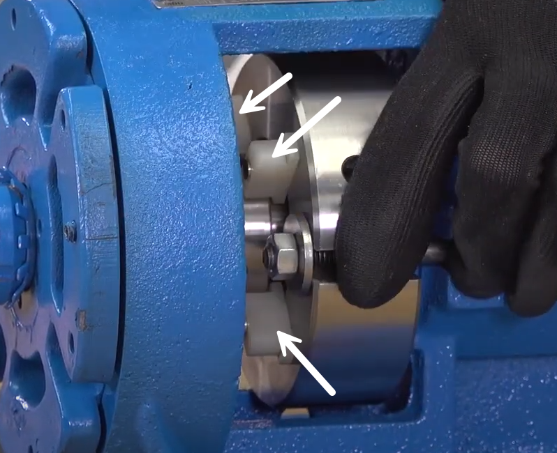 |
| 10. Reconnect seal plan or plug unused connections. | |


October 06, 2025

August 15, 2025

March 25, 2025