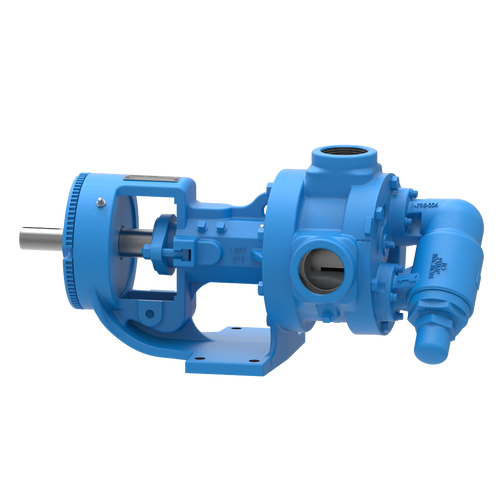
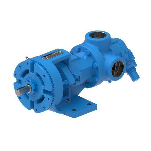
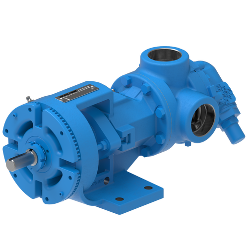
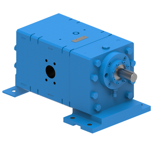
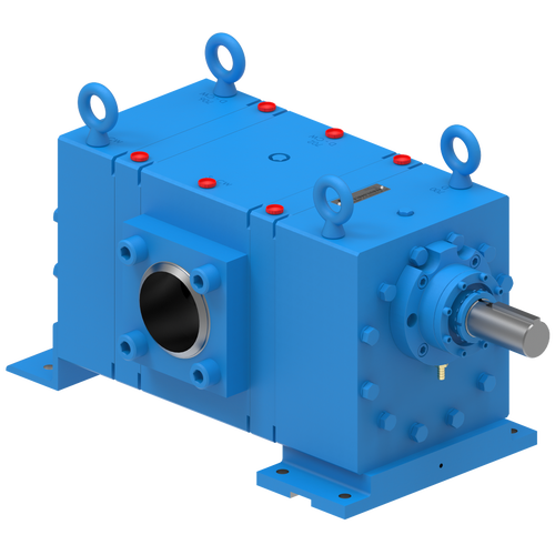
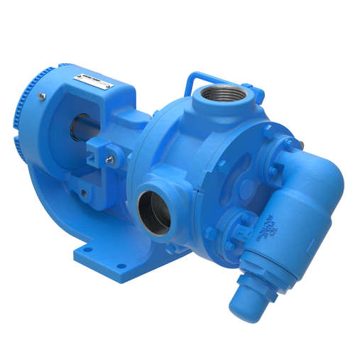
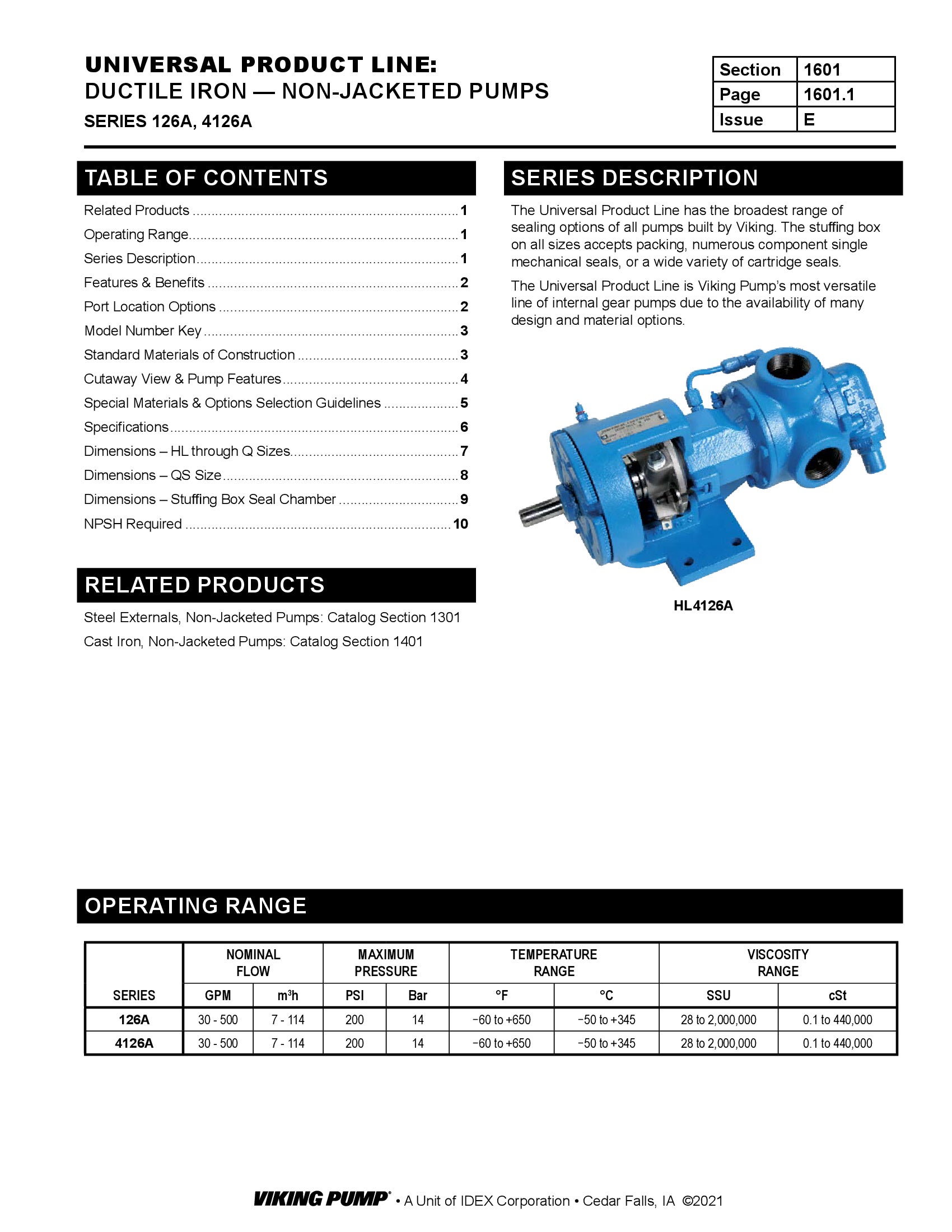
The 126A Series™ internal gear pump is the most versatile line of internal gear pumps due to the availability of many design and other options. It can handle a broad range of viscosities with constant flow rate up to 500 GPM (114 m³/h).
Features & Benefits
- Positive displacement internal gear pumping principle handles a broad range of viscosities with constant flow rate
- Axial rotor thrust is controlled by double row ball bearing or tapered roller bearings; a bushing provides a secondary point of radial shaft support
- Rotatable bearing housing provides easy rotor end clearance adjustment for viscosity or to compensate wear
Videos
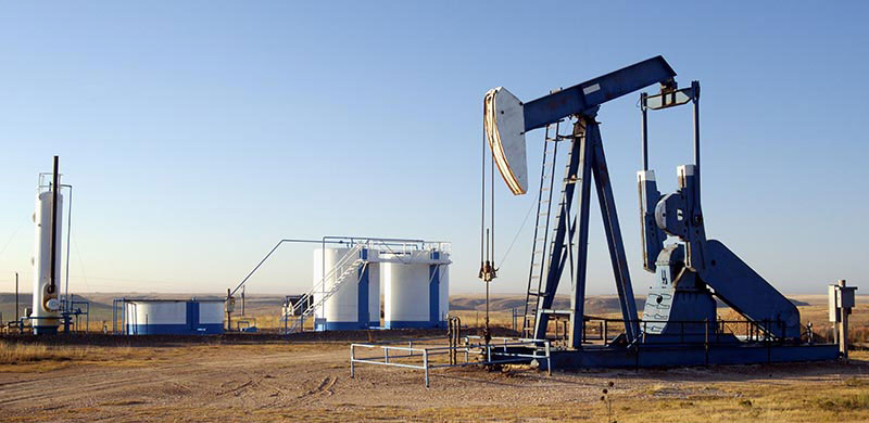
Crude Oils
This is a very generic term for unrefined oils typically being recovered from the ground. Some crude oil may contain particulates from the oil well or recovery method. They are considered to be flammable liquids. Crude oils are later refined and used for everything from making plastics to gasoline.
TSM / Catalog / Flyers / Brochures
Service Manual | 1600
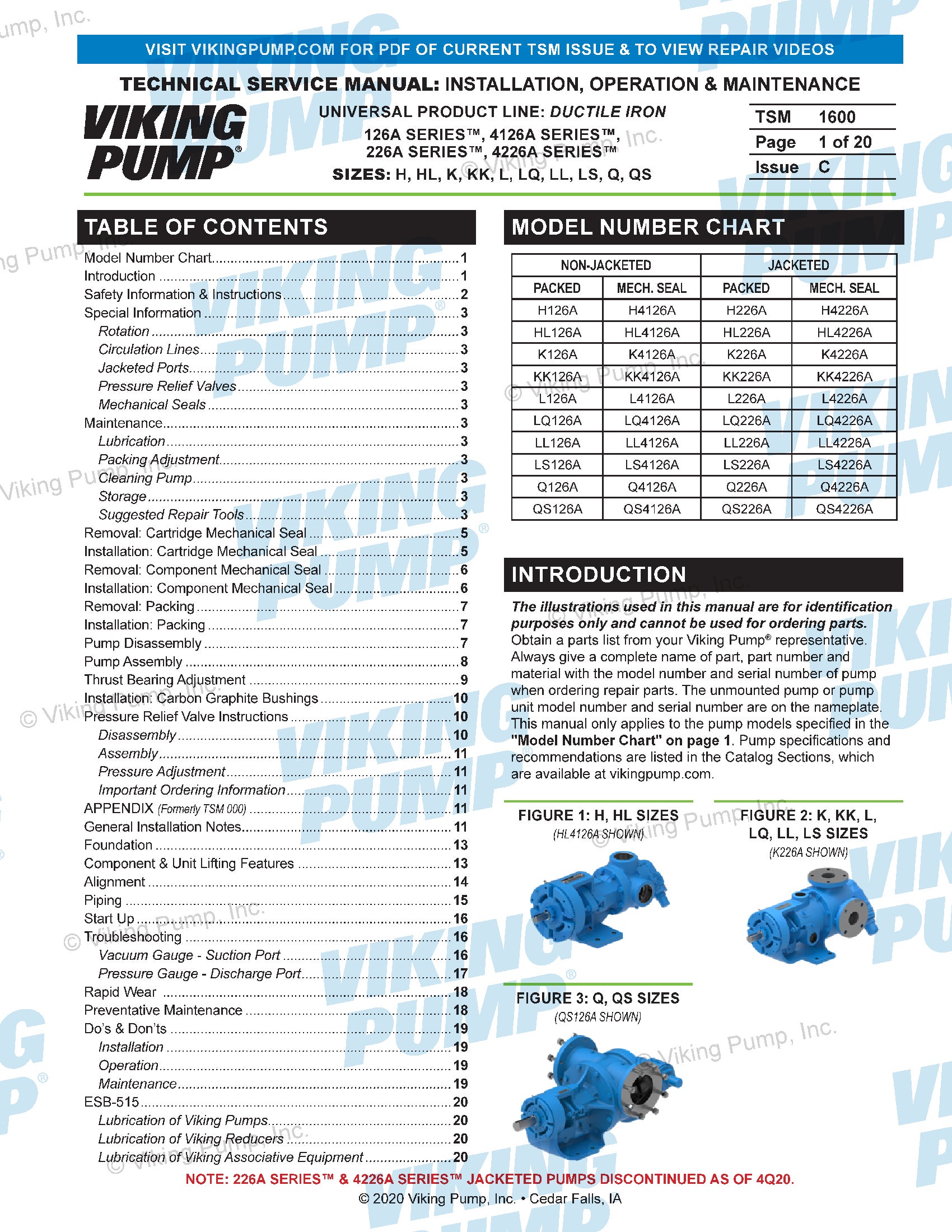
Technical Service Manuals
Catalog Section | 1601 | Non-Jacketed
Catalog Sections
-
REPAIR RESOURCES

Exploded Diagram for Series 123A/4123A - 124A/ 4124A - 126A/4126A - 127A/4127A … 
Quick Tip #01 - Setting End Clearance on a Viking Pump Universal Seal Pump 
Updated: Quick Tip #03 - Install Packing into a Viking Pump
How to Use a Thrust Bearing Locknut Tool
Viking Pump Universal Seal Series with Stuffing Box Component Seals Repair Kit Installation
Quick Tip #02 - Install Mechanical Seal into Stuffing Box in Viking Pump Universal Seal Pump
Viking Pump Universal Seal Series with Packing Seal Disassembly, Repair & Reassembly
-
DRAWINGS
H-HL with Plain Head - 1.5" NPT RH/LH
PDF
H-HL with Relief Valve - 1.5" NPT RH/LH
PDF
H-HL with RV and ProPort Casing - DIN 40 PN16 Opposite
PDF
K-KK with Plain Head - 2" Class 150 RH/LH
PDF
K-KK with Plain Head - 2" NPT RH/LH
PDF
K-KK with Relief Valve - 2" Class 150 RH/LH
PDF
K-KK with Relief Valve - 2" NPT RH/LH
PDF
L with Plain Head - 2" NPT RH
PDF
L with Relief Valve - 2" NPT RH
PDF
LL with Plain Head - 3" Class 125 ANSI RH/LH
PDF
LL with Relief Valve - 3" Class 125 ANSI RH
PDF
LQ with Plain Head - 2.5" Class 125 ANSI RH/LH
PDF
LQ with Relief Valve - 2.5" Class 125 ANSI RH/LH
PDF
LS with Plain Head - 3" Class 125 ANSI RH/LH
PDF
LS with Relief Valve - 3" Class 125 ANSI RH
PDF
Q with Relief Valve - 4" Class 150 ANSI RH/LH with Studs and Bolts
PDF
QS with Plain Head - 4" Class 125 ANSI RH/LH
PDF
QS with Plain Head - 6" Class 125 ANSI Opposite
PDF
QS with Relief Valve - 6" Class 150 ANSI Opposite
PDF
QS with Relief Valve - 6" Class 150 ANSI RH
PDF