 United Kingdom
 France
 Italy
Italy
 Germany
 Sweden
 Spain
Spain
 Canada
 India
India


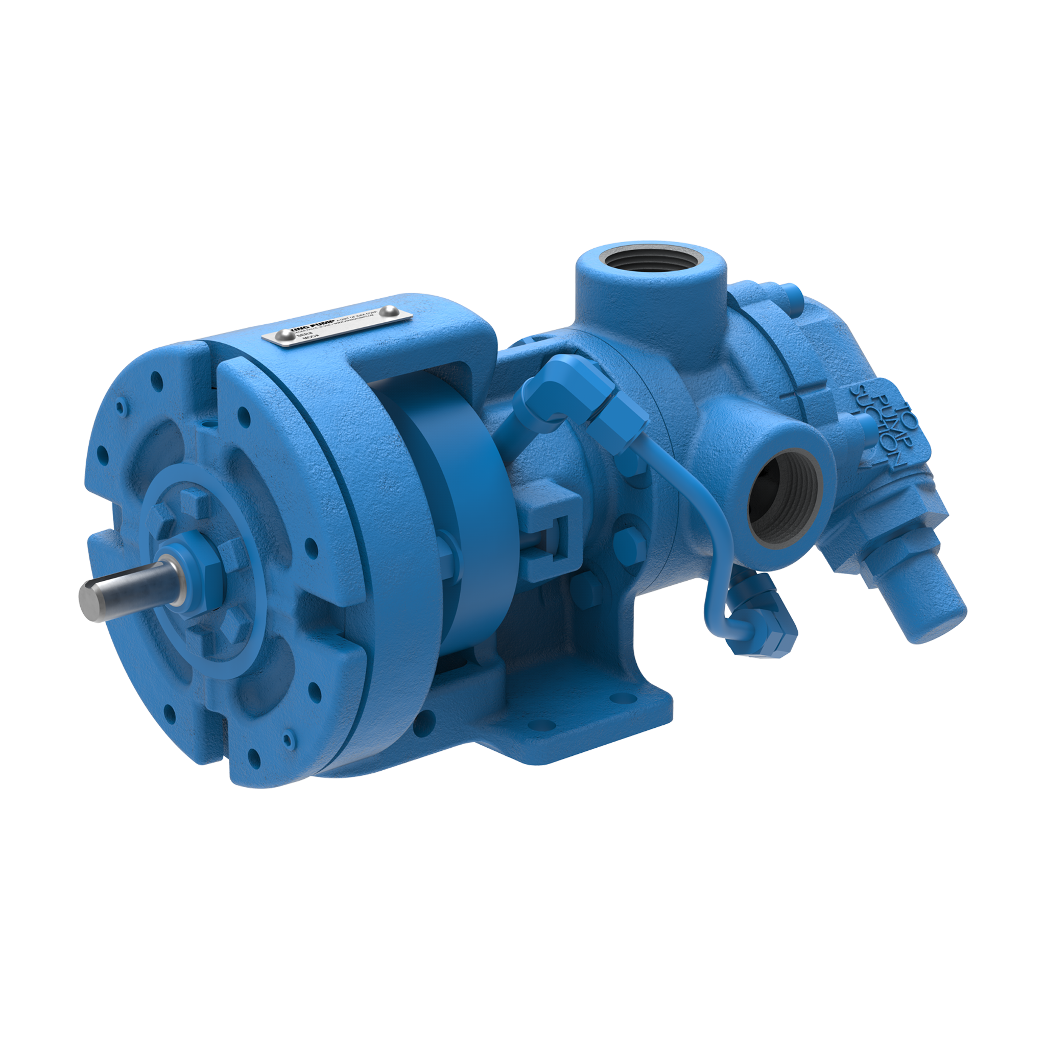
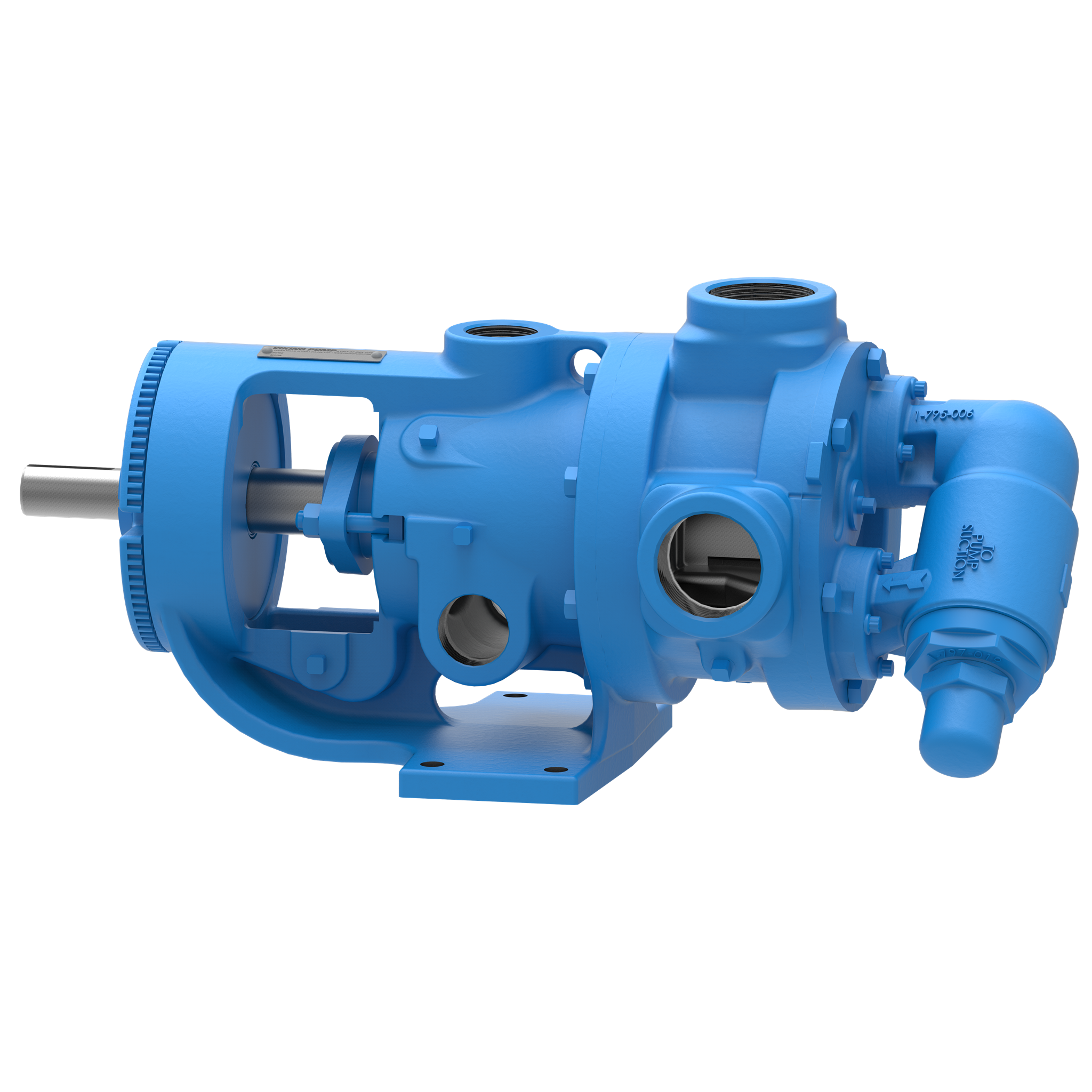
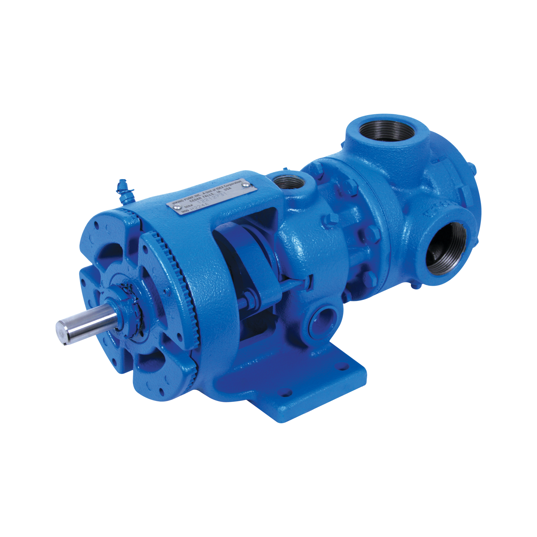
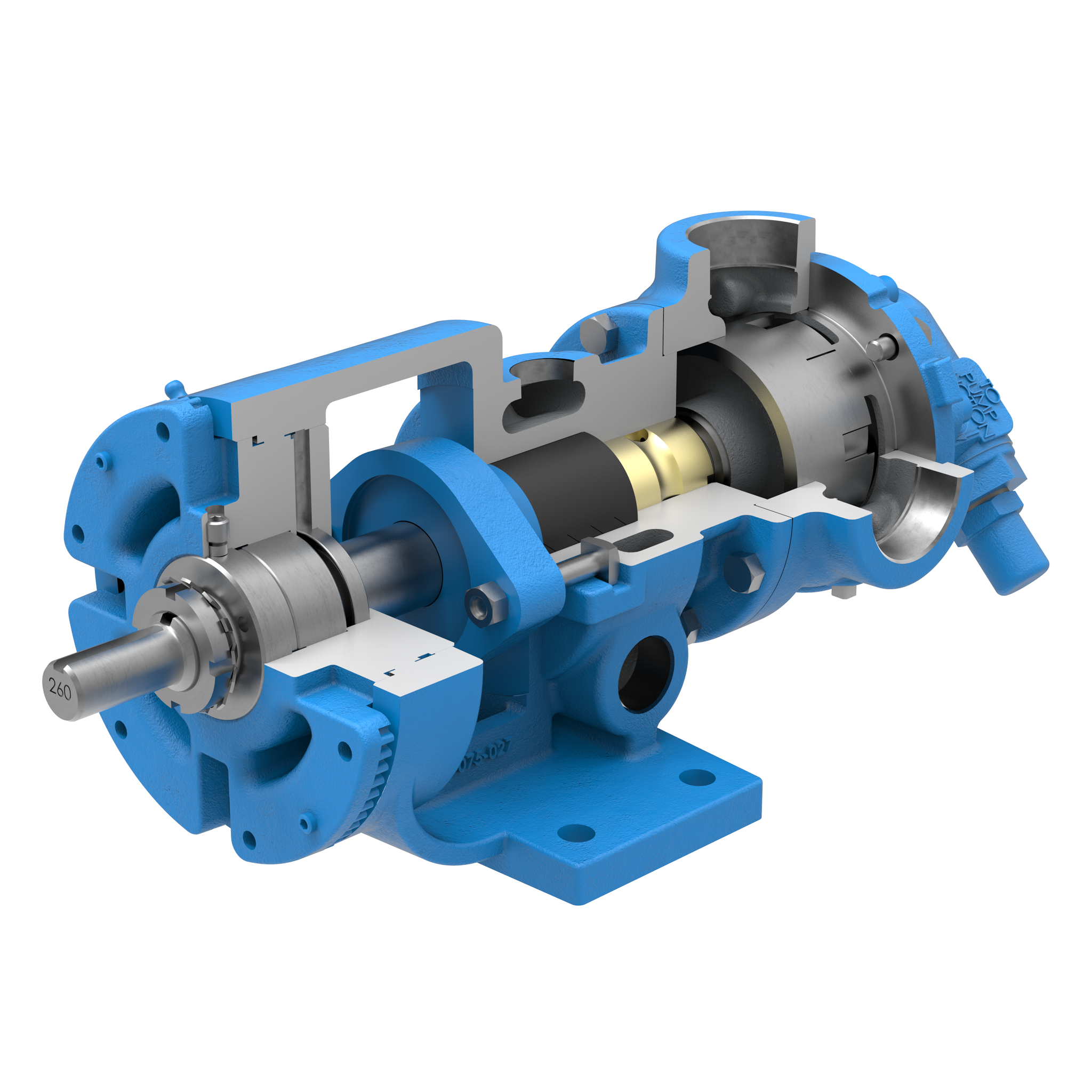
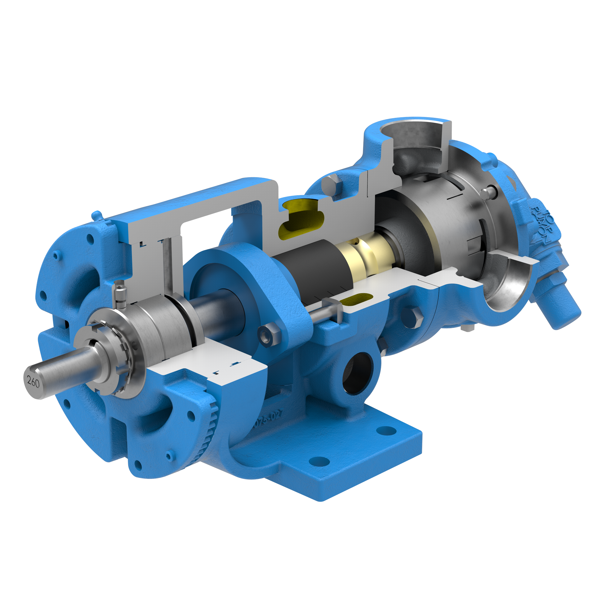
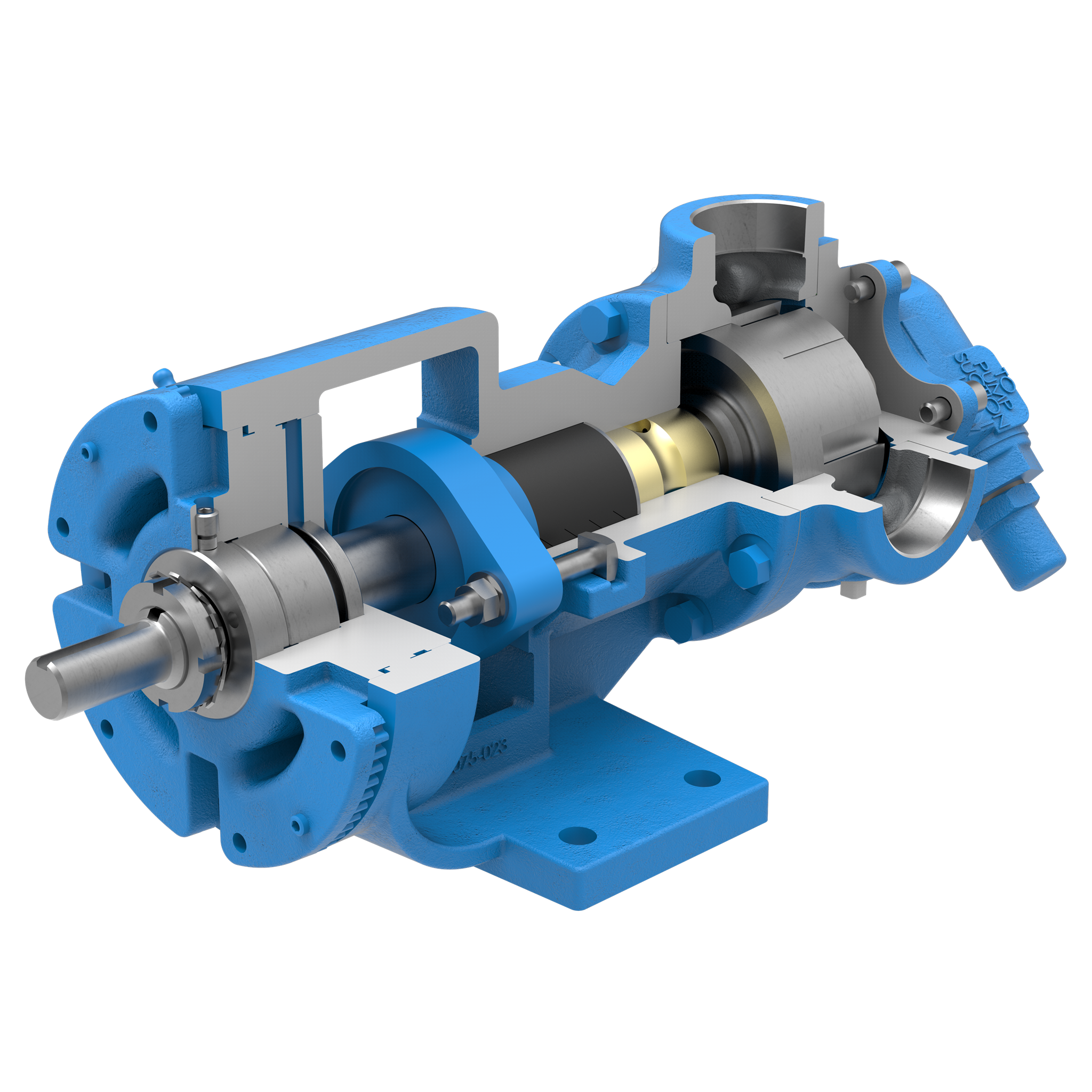
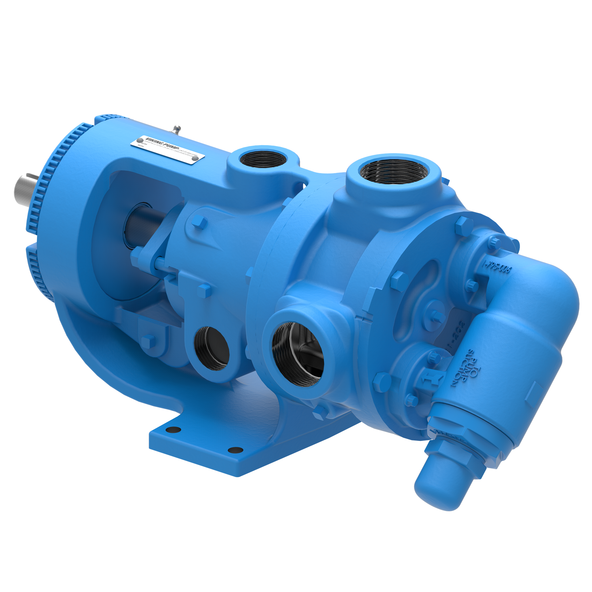
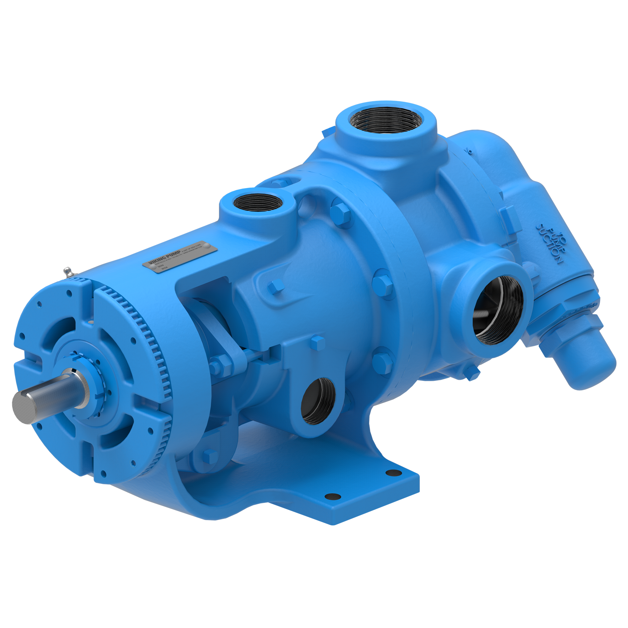
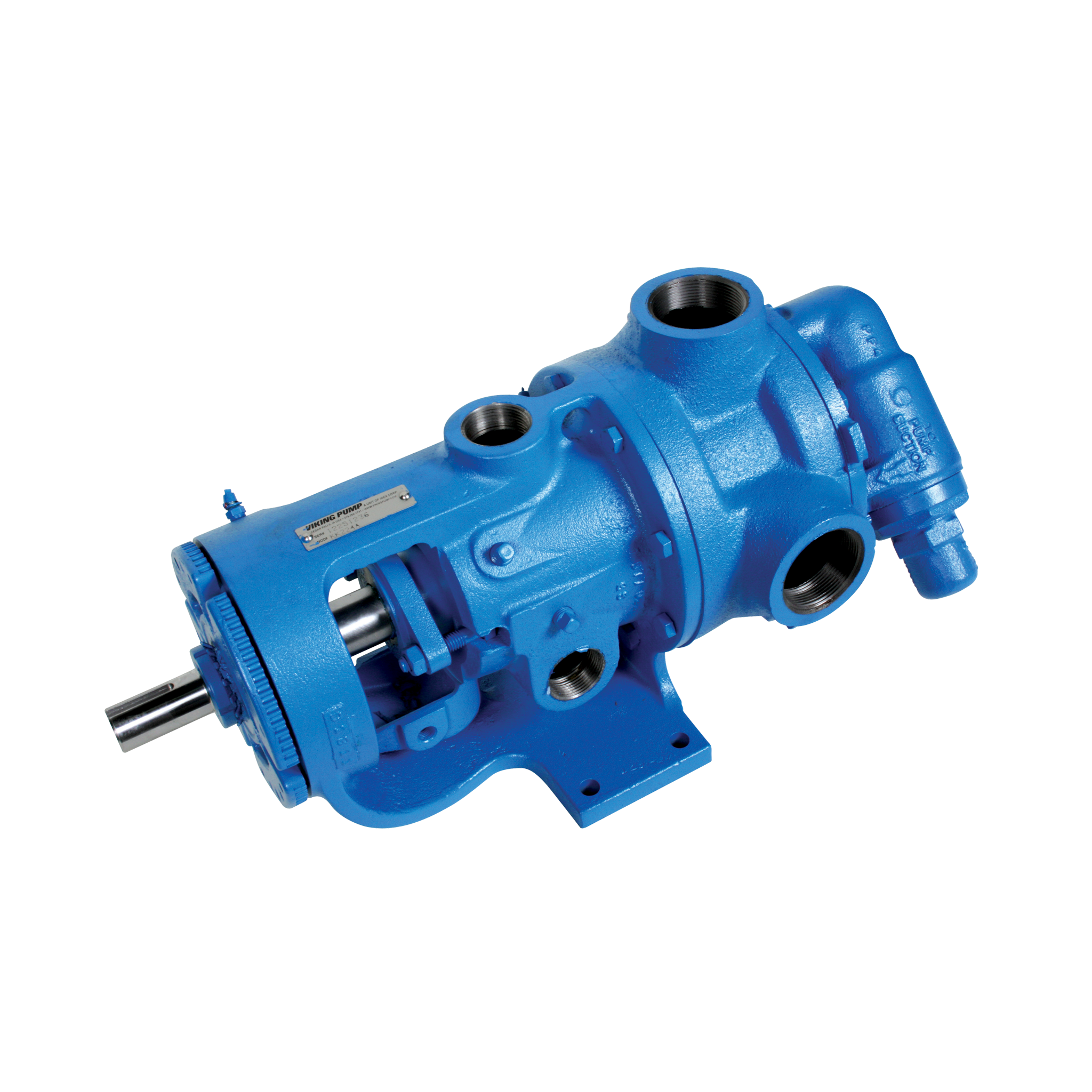
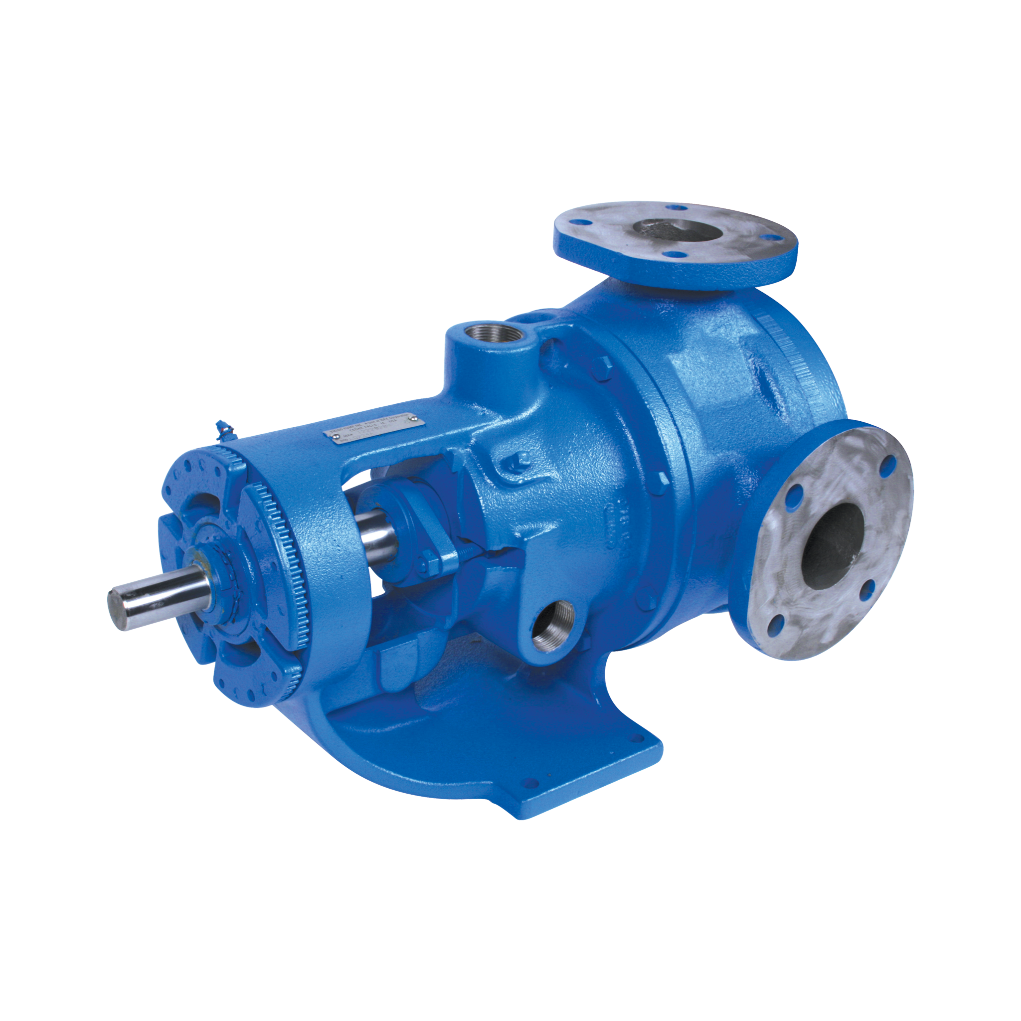
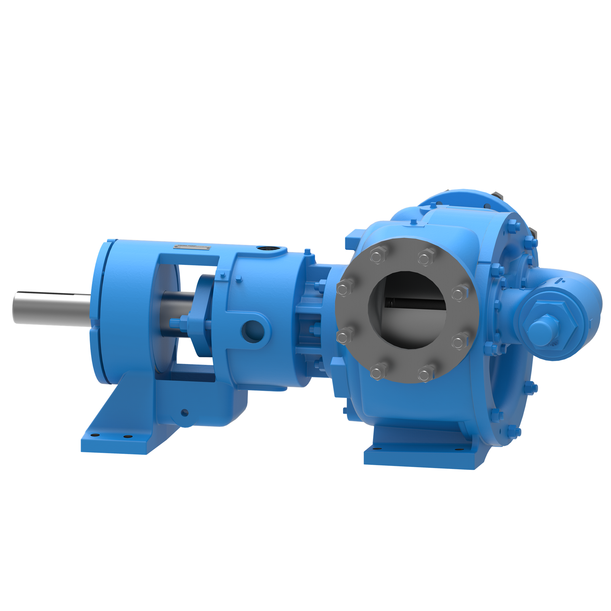
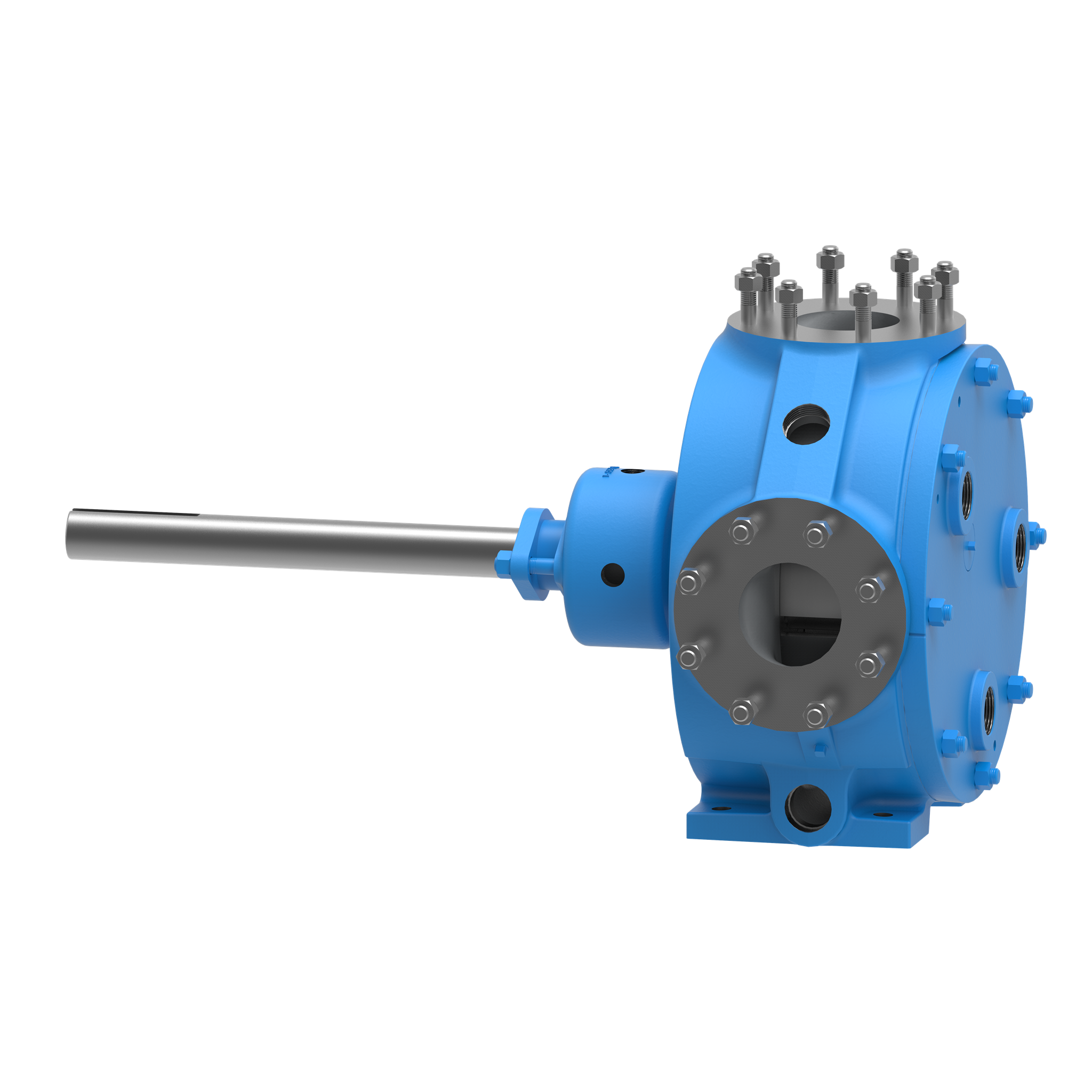
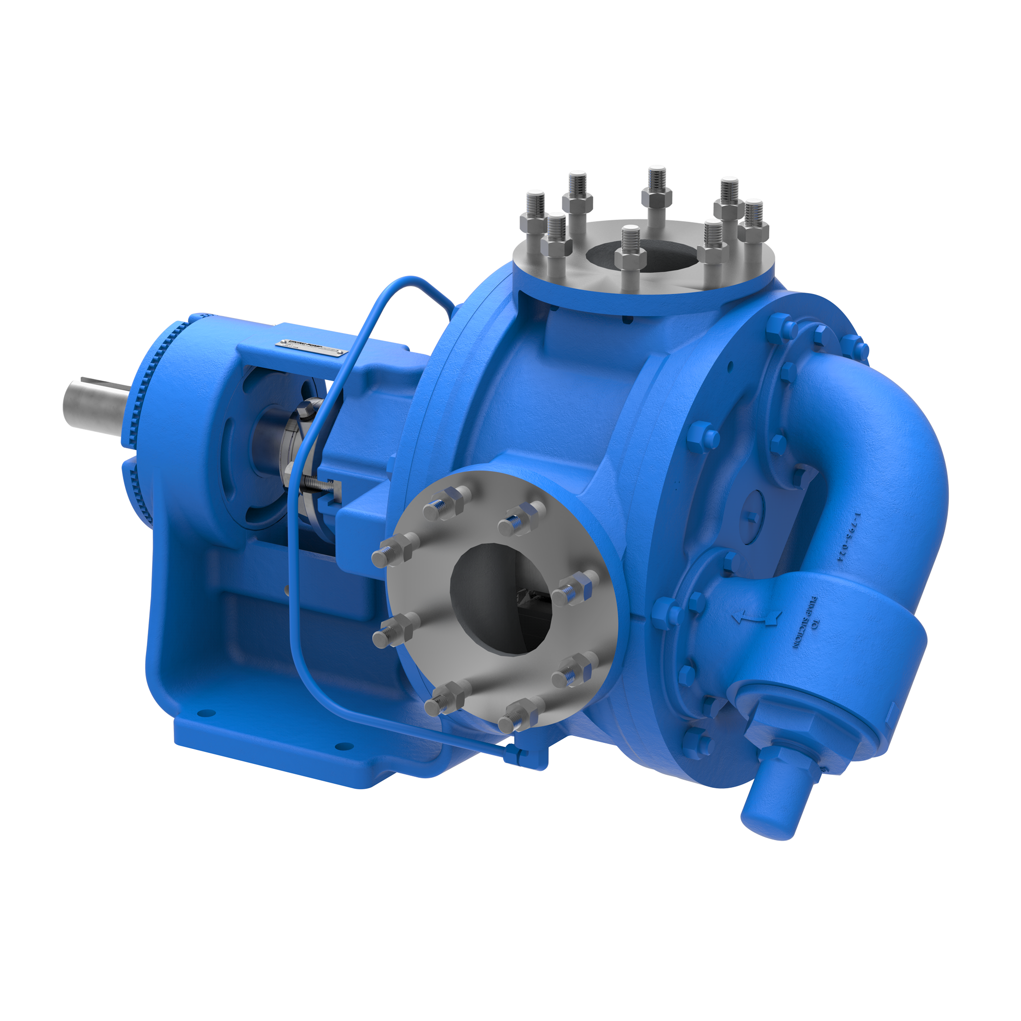
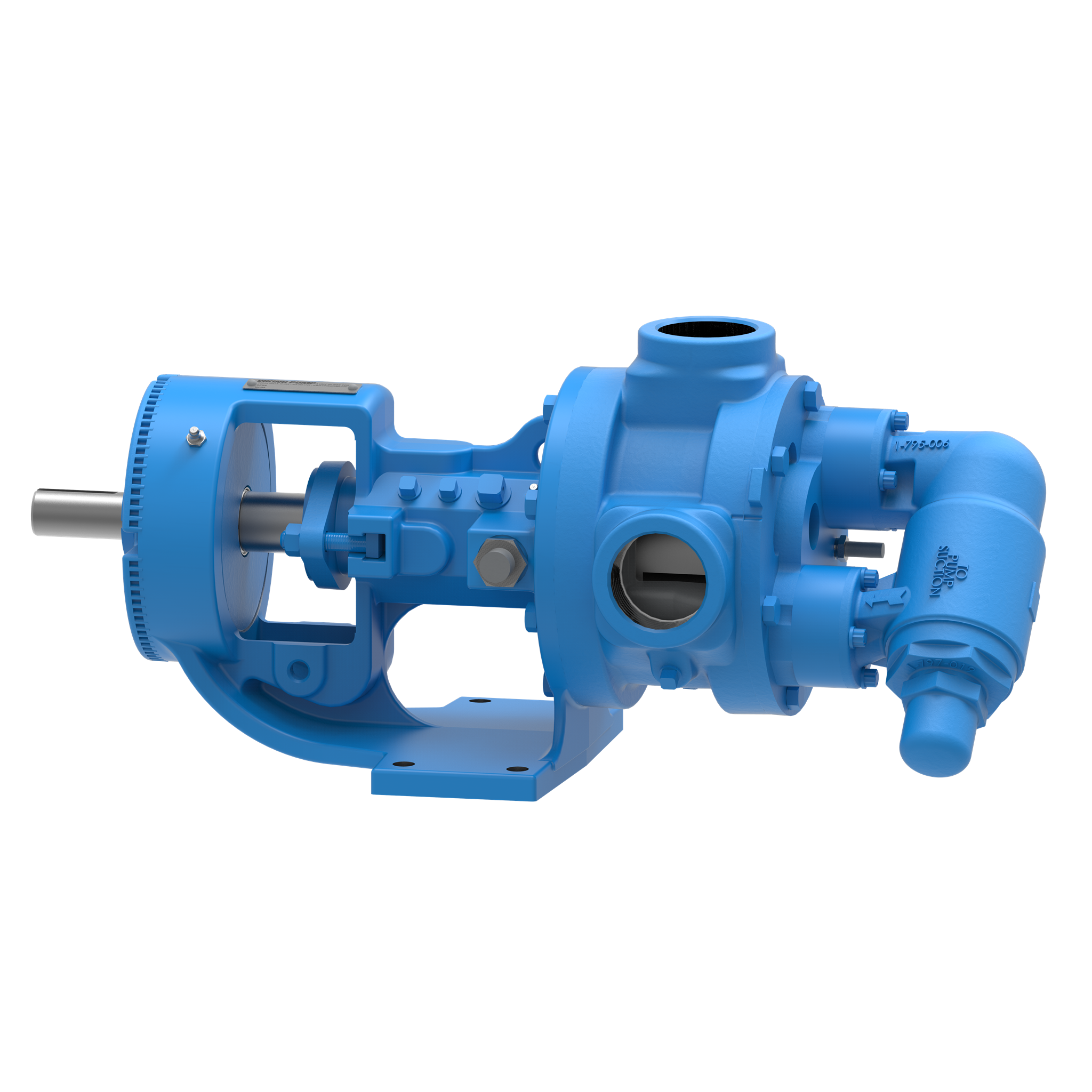
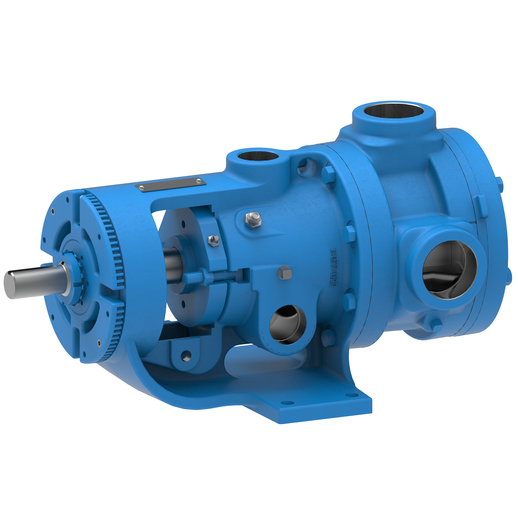
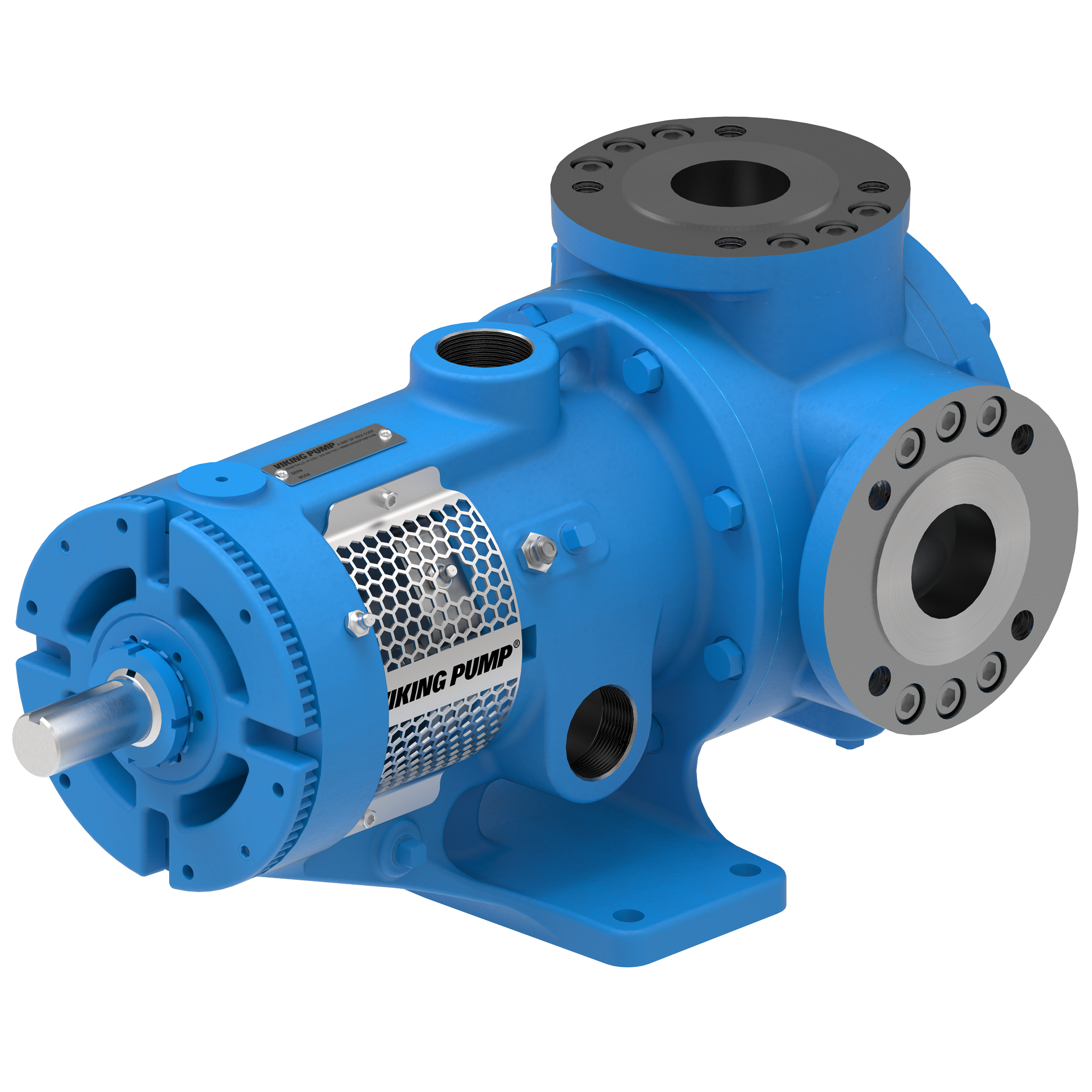
La bomba de engranaje interno 224A Series™ es la solución perfecta para fuelóleo pesado, ceras, soluciones de caucho y mucho más, gracias a su capacidad para calentarse de forma rápida y eficiente utilizando vapor o aceite caliente. Puede manejar caudales de hasta 500 GPM (114 m³/h).
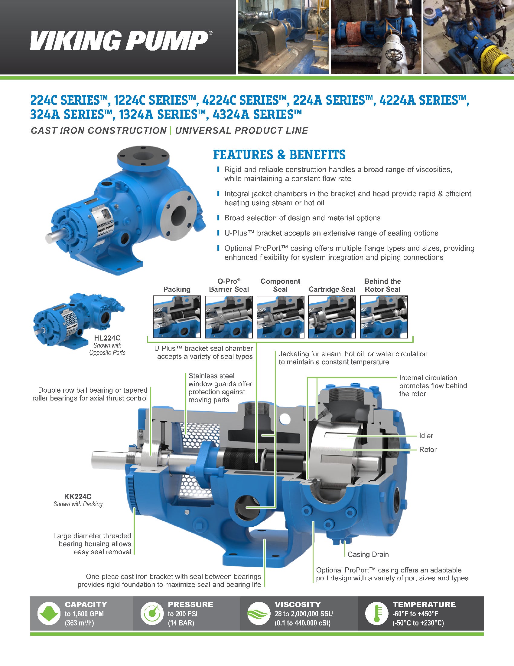
Características y ventajas
- Resistente y fiable, pero económico
- La más amplia gama de tamaños y opciones disponibles para adaptarse a casi cualquier aplicación no corrosiva
- Las cámaras de camisa integradas en el soporte y el cabezal rodean la junta y los componentes internos de la bomba para un calentamiento rápido y eficiente mediante vapor o aceite caliente
Photos
Videos








TSM / Catalog / Flyers / Brochures
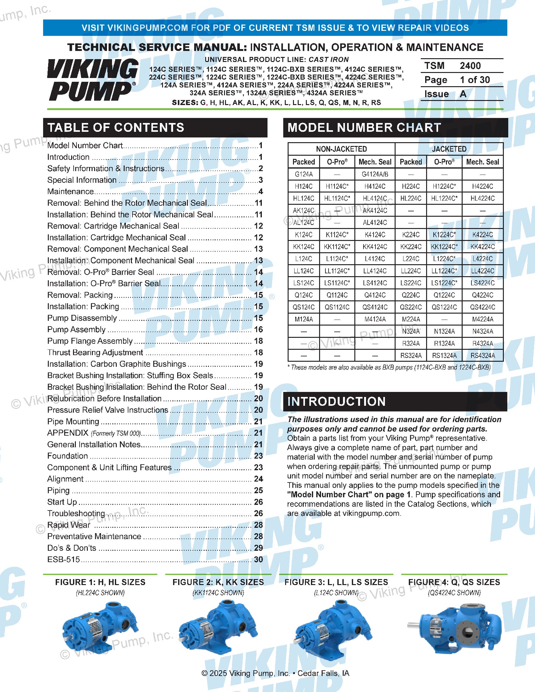
Service Manual | 2400
Technical Service Manuals
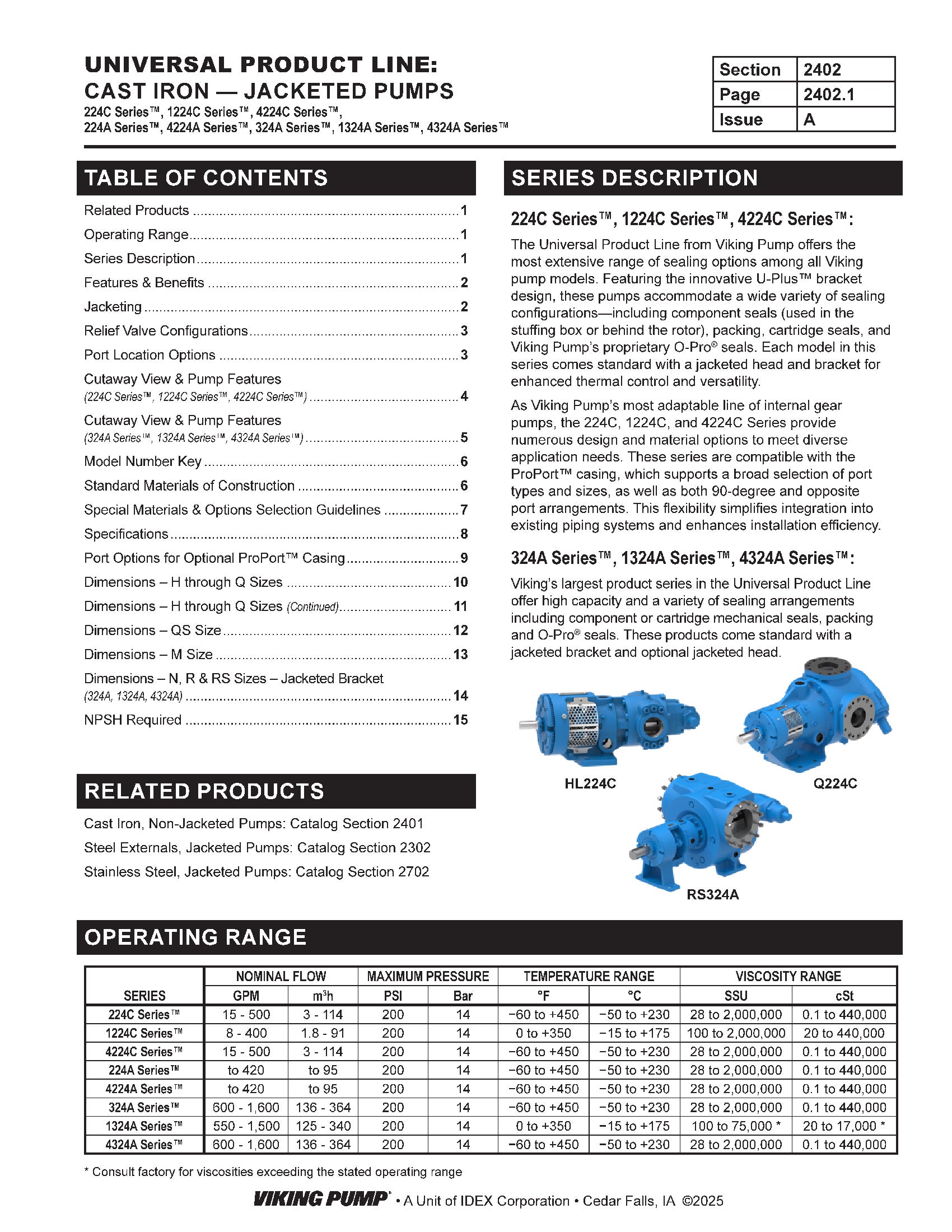
Catalog Section | 2402 | Jacketed
Catalog Sections
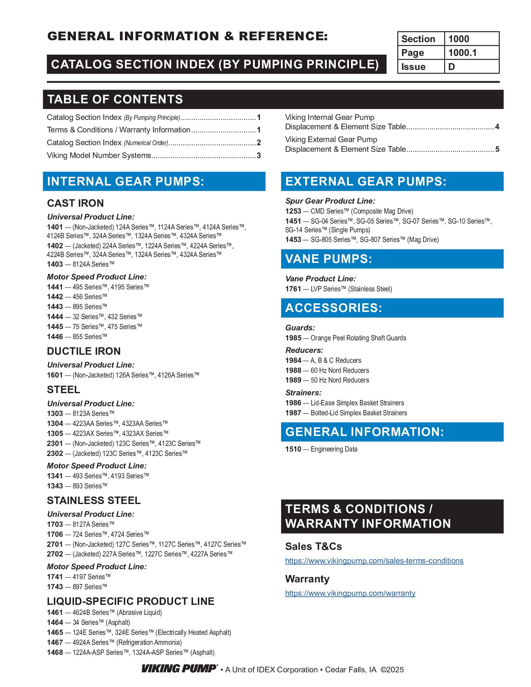
Catalog Section | 1000 | General Information
Product Flyers
Flyer | Form 2402 Jacketed
Product Flyers
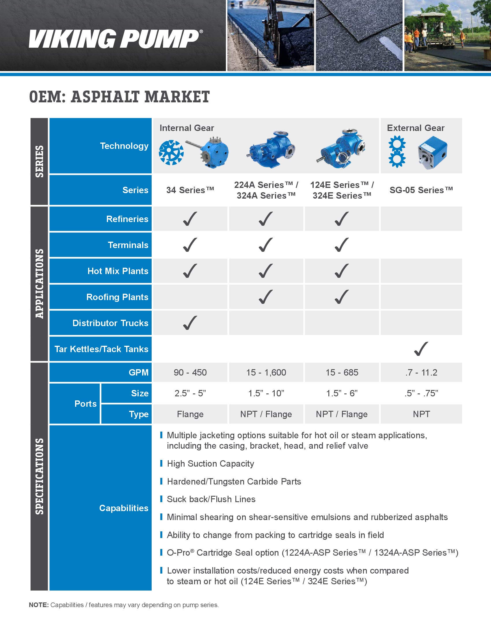
OEM Flyer | Asphalt
Product Flyers
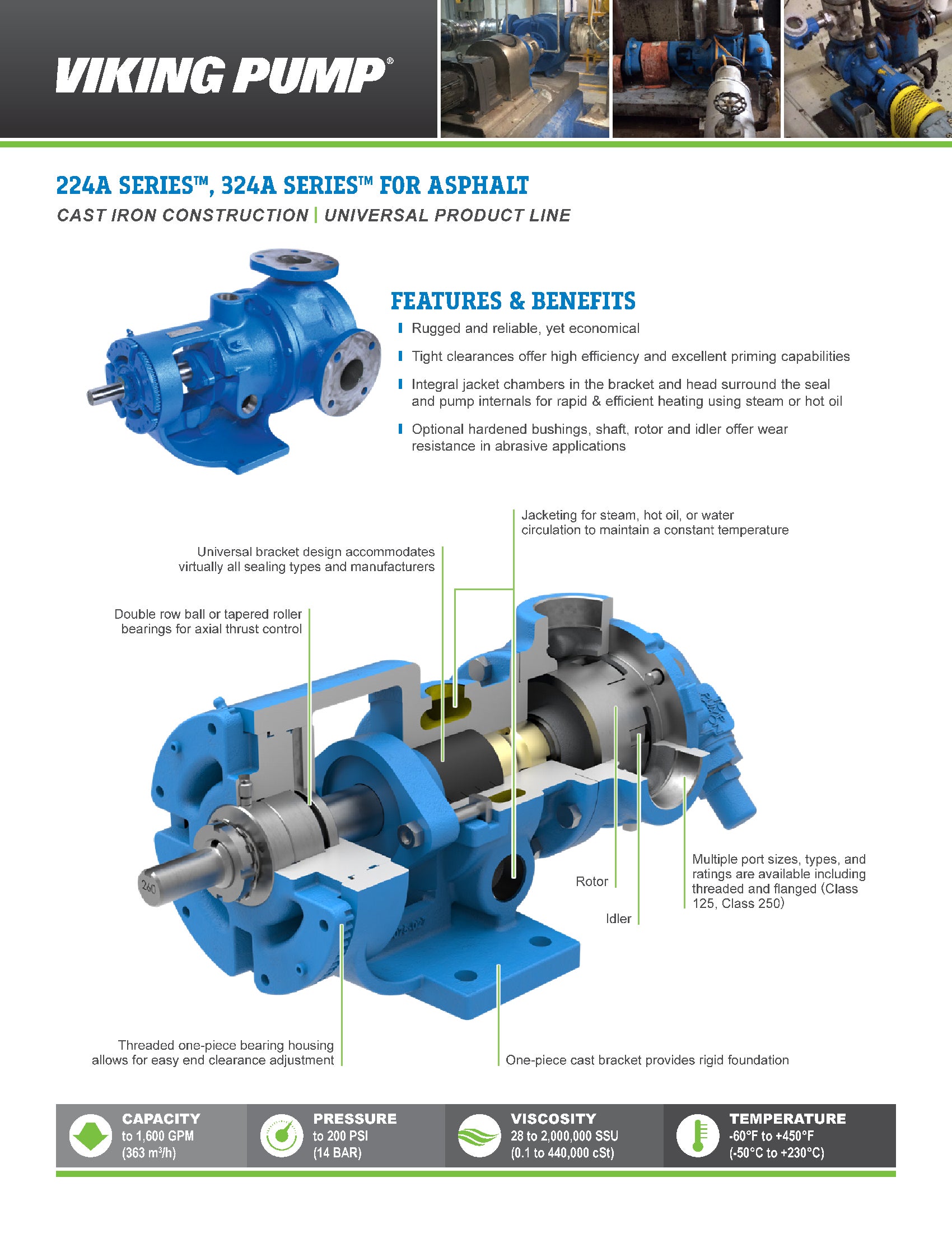
Flyer | Form 1402-Asphalt | 224A / 324A Series
Product Flyers
Form 5000 | Product Catalog

-
DRAWINGS

H-HL with Relief Valve - 1.5" Class 125 ANSI RH/LH  PDF
PDF
H-HL with Relief Valve - 1.5" NPT RH
PDF
 STEP
STEP
K-KK with Plain Head - 2" NPT RH/LH
PDF
STEP
K-KK with Plain Head - 3" Class 125 ANSI RH
PDF
STEP
K-KK with Relief Valve - 2" NPT RH
PDF
STEP
L with Jacketed Relief Valve - 2" NPT RH
PDF
STEP
L with Jacketed Relief Valve - 3" Class 125 ANSI RH
PDF
STEP
L with Plain Head - 2" NPT RH
PDF
STEP
L with Relief Valve - 2" NPT RH/LH
PDF
STEP
LL with Jacketed Relief Valve - 3" Class 125 ANSI RH
PDF
STEP
LL with Plain Head - 3" Class 125 ANSI RH/LH
PDF
STEP
LL with Relief Valve - 3" Class 125 ANSI RH/LH
PDF
STEP
LQ with Jacketed Relief Valve - 2.5" Class 125 ANSI RH
PDF
STEP
LQ with Plain Head - 2.5" Class 125 ANSI RH/LH
PDF
STEP
LQ with Relief Valve - 2.5" Class 125 ANSI RH/LH
PDF
STEP
LS with Plain Head - 3" Class 125 ANSI RH/LH
PDF
STEP
LS with Relief Valve - 3" Class 125 ANSI RH/LH
PDF
STEP
M with Jacketed Relief Valve - 4" Class 125 ANSI RH
PDF
STEP
M with Plain Head - 4" Class 125 ANSI RH
PDF
STEP
M with Relief Valve - 4" Class 125 ANSI RH
PDF
STEP
Q with Jacketed Head - 4" Class 125 ANSI RH/LH
PDF
STEP
Q with Jacketed Relief Valve - 4" Class 125 ANSI RH
PDF
STEP
Q with Relief Valve - 4" Class 125 ANSI RH/LH
PDF
STEP
QS with Jacketed Head - 6" Class 125 ANSI Opposite
PDF
STEP
QS with Jacketed Relief Valve - 6" Class 125 ANSI Opposite
PDF
STEP
QS with Relief Valve - 6" Class 125 ANSI Opposite
PDF
STEP