 United Kingdom
 France
 Italy
Italy
 Germany
 Sweden
 Spain
Spain
 Canada
 India
India


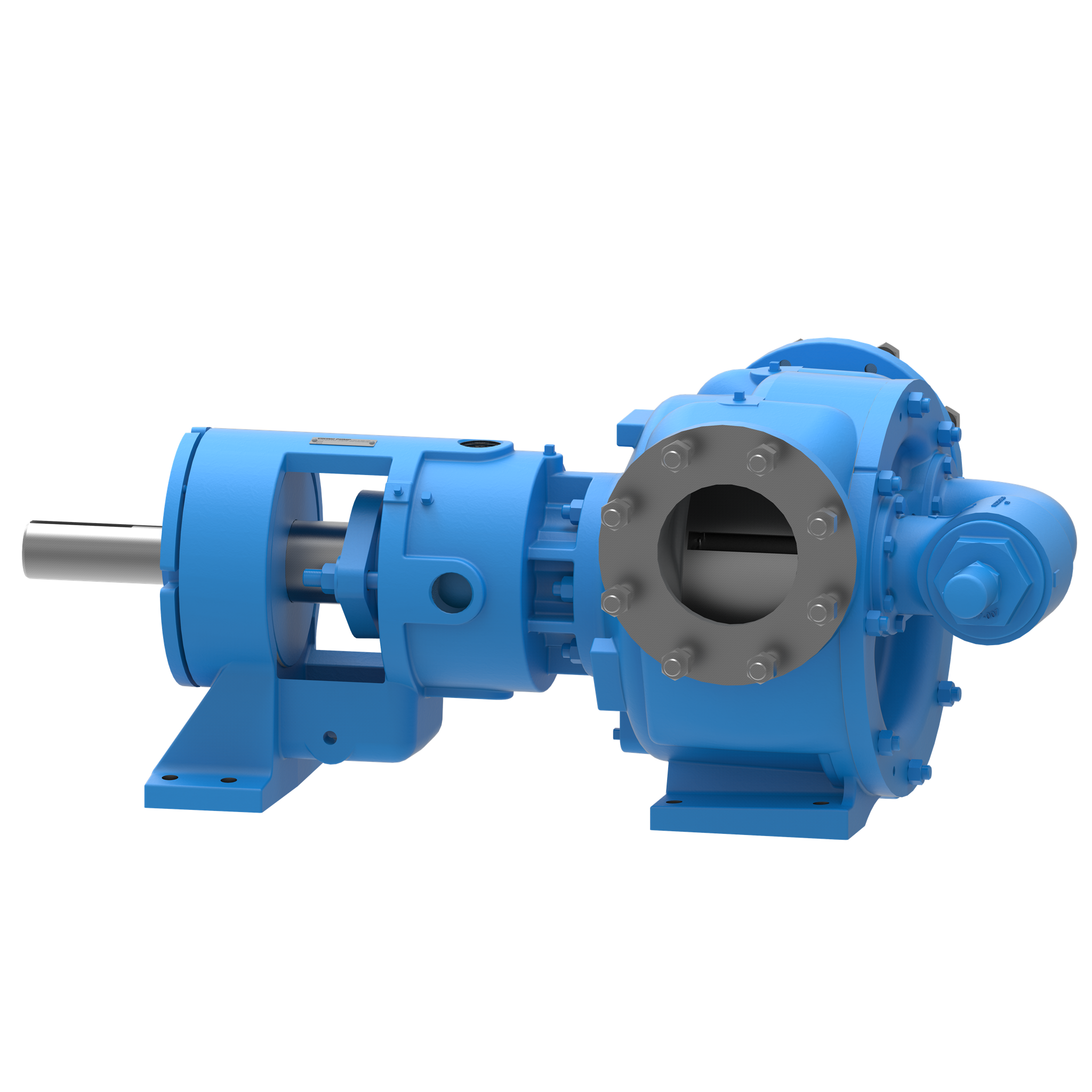
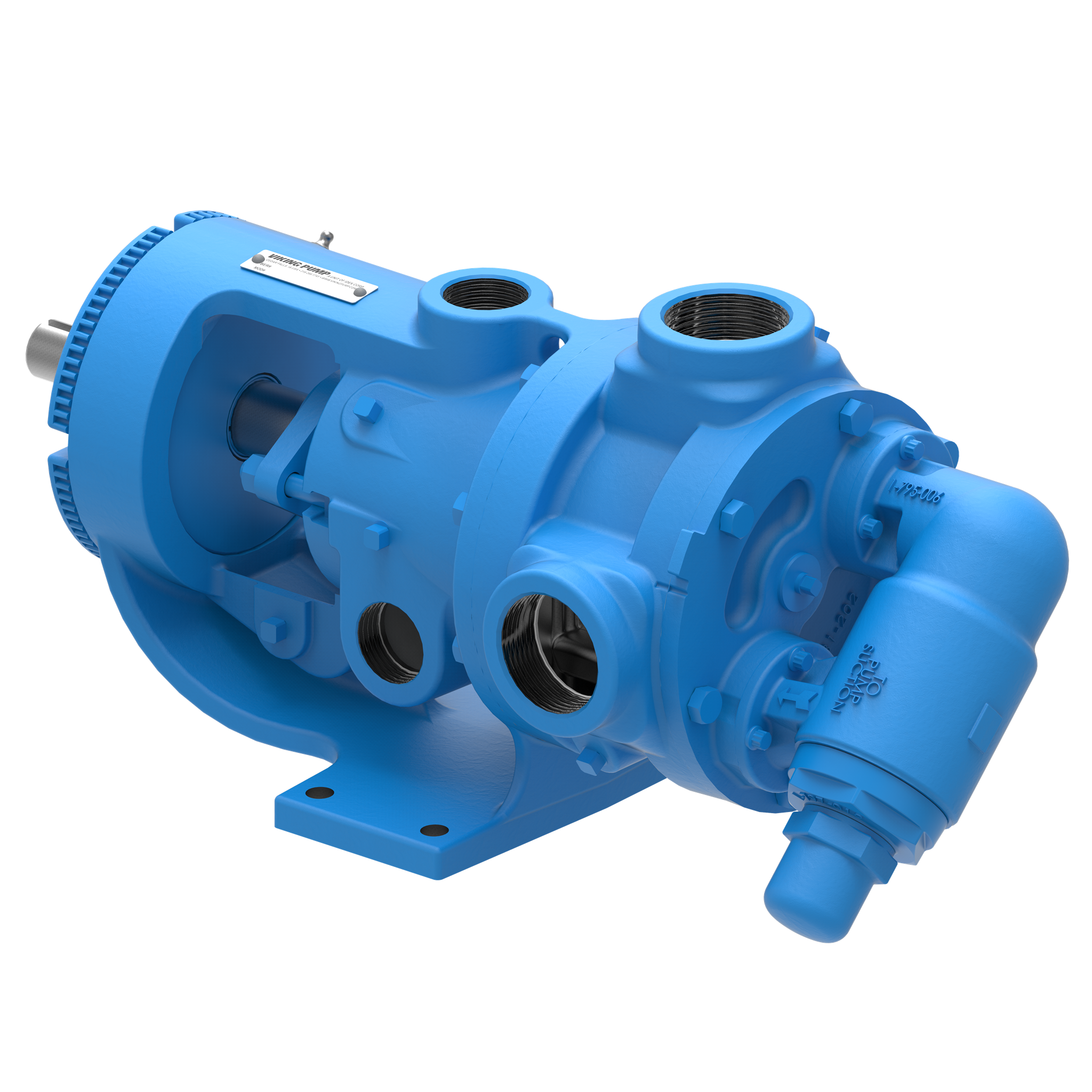
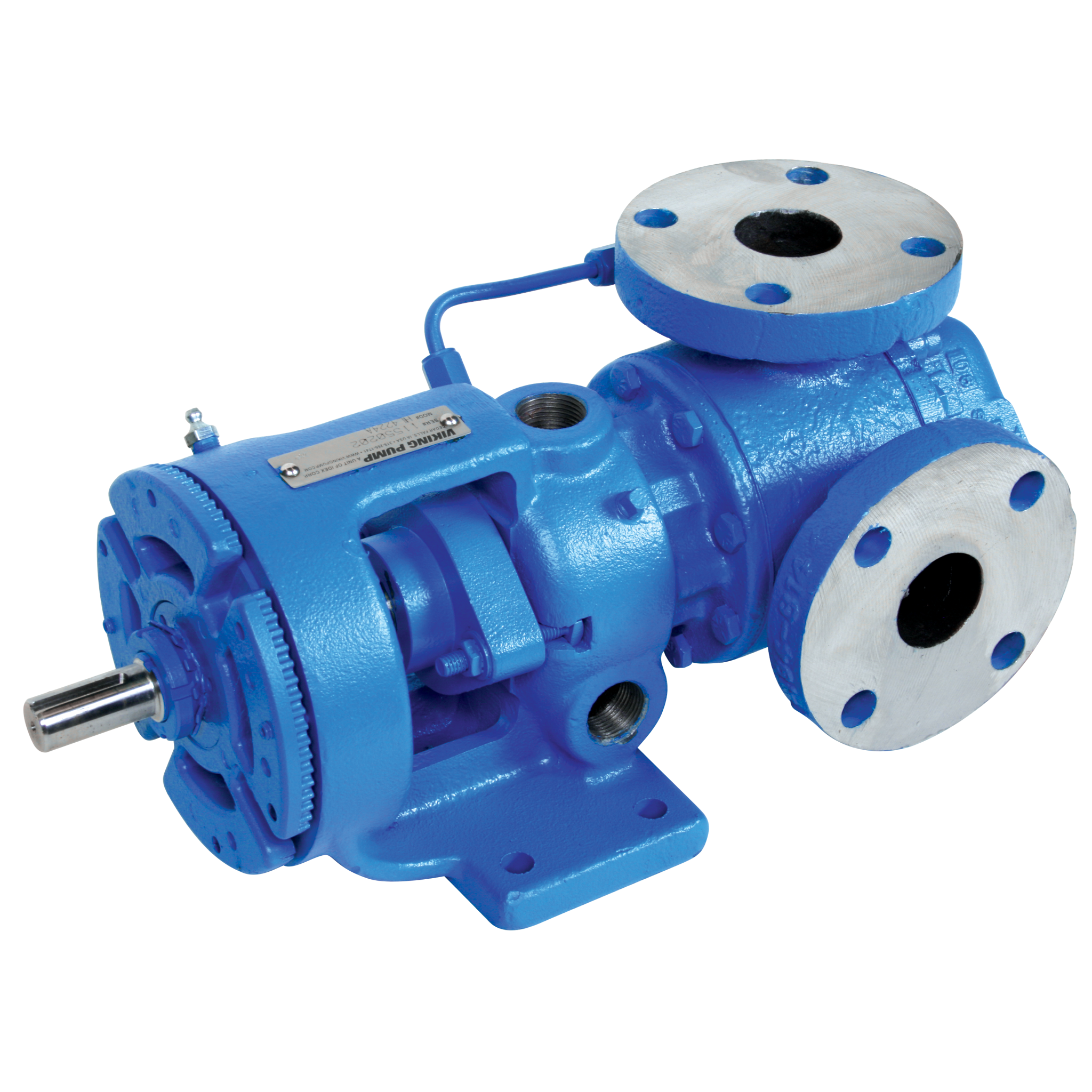
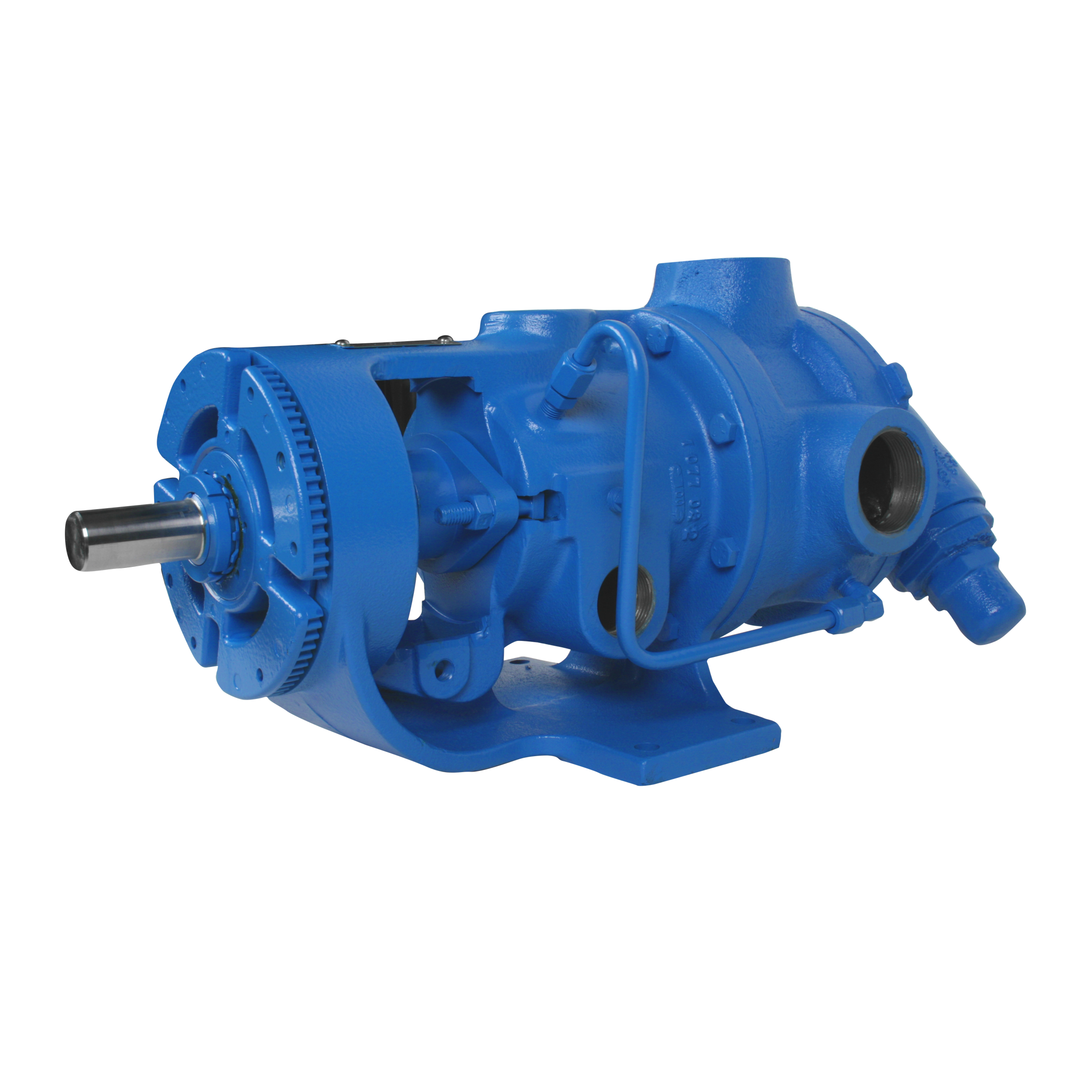
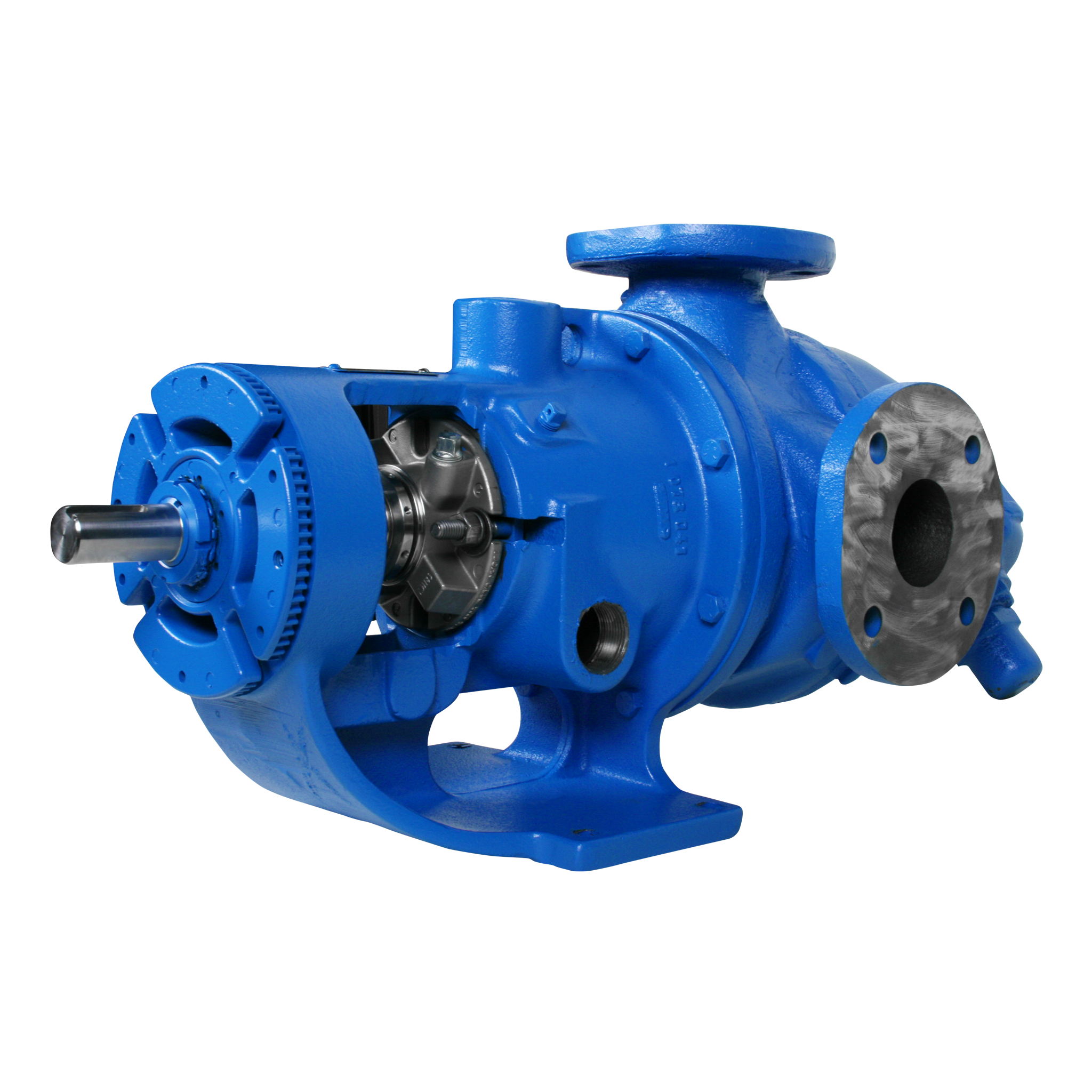
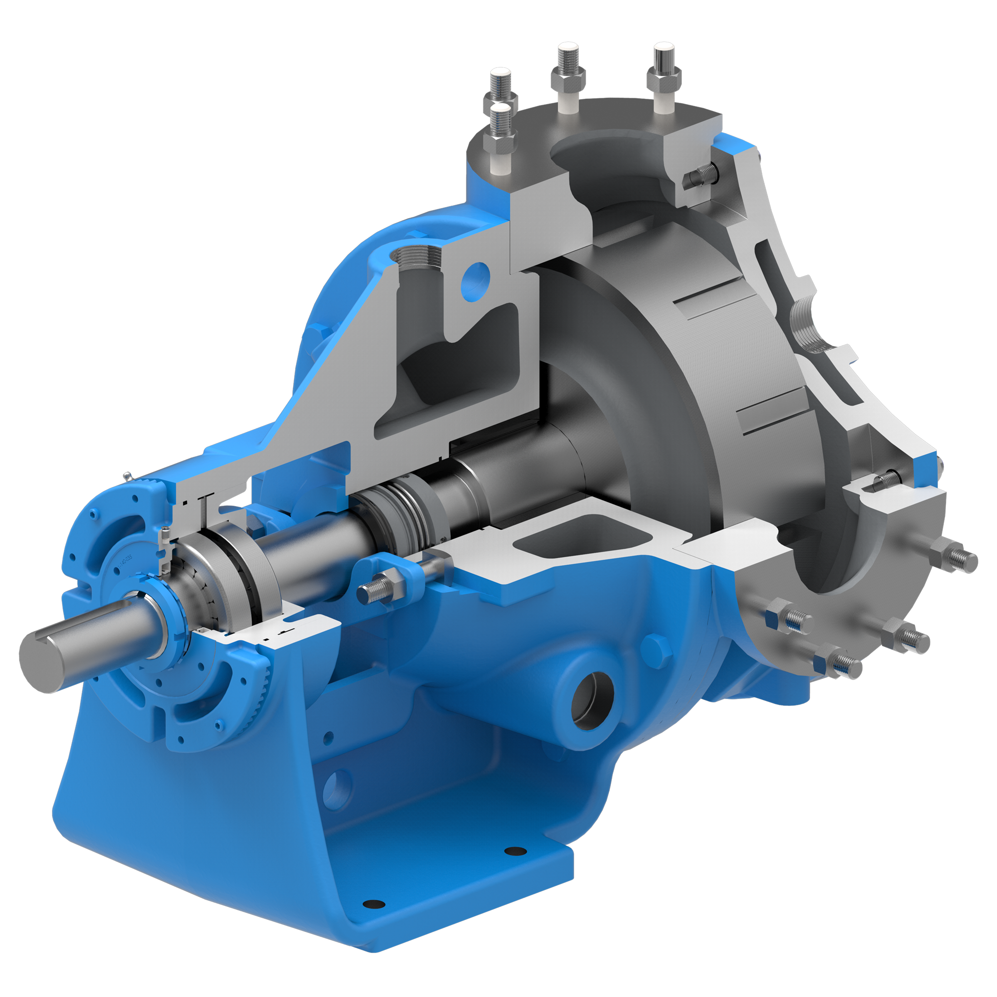
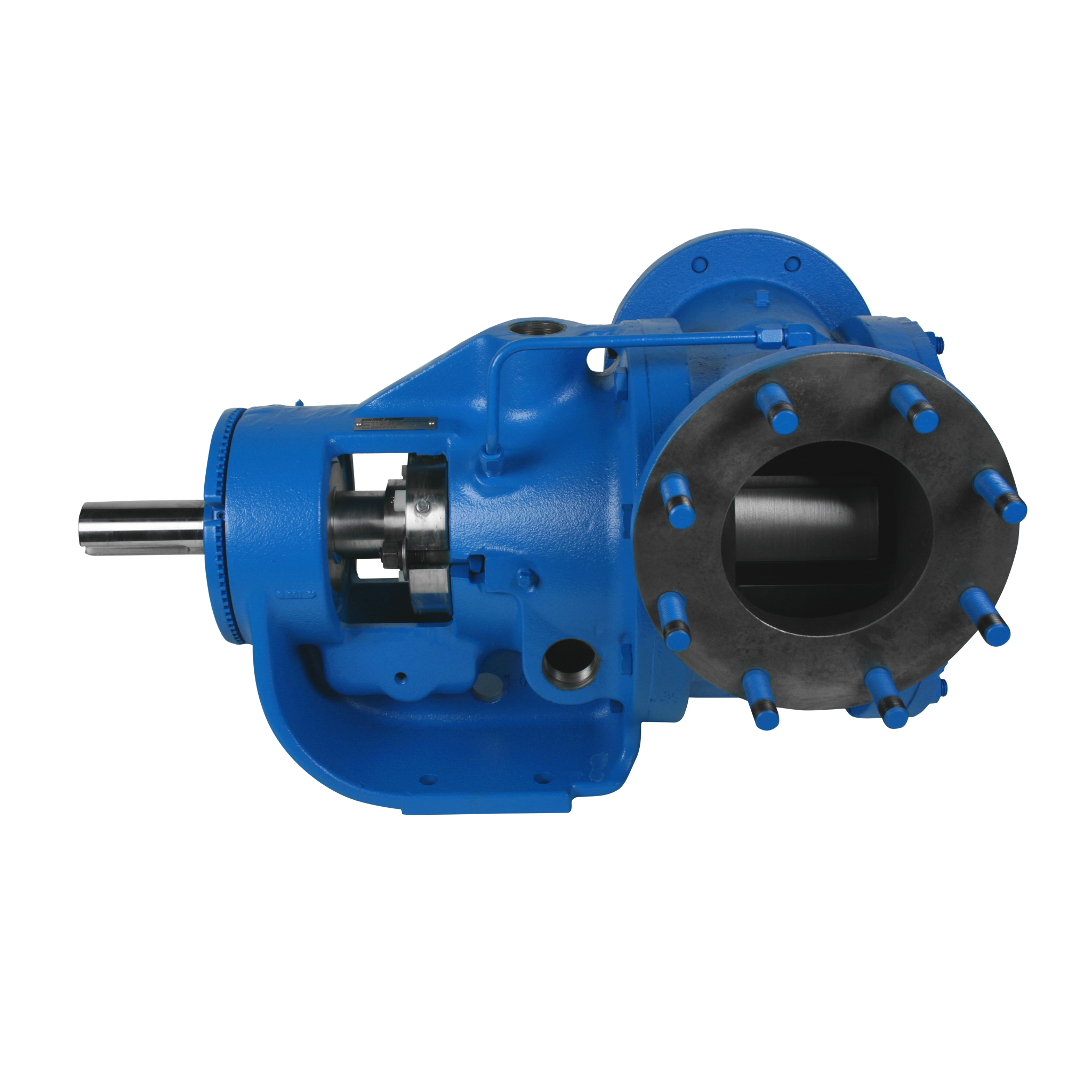
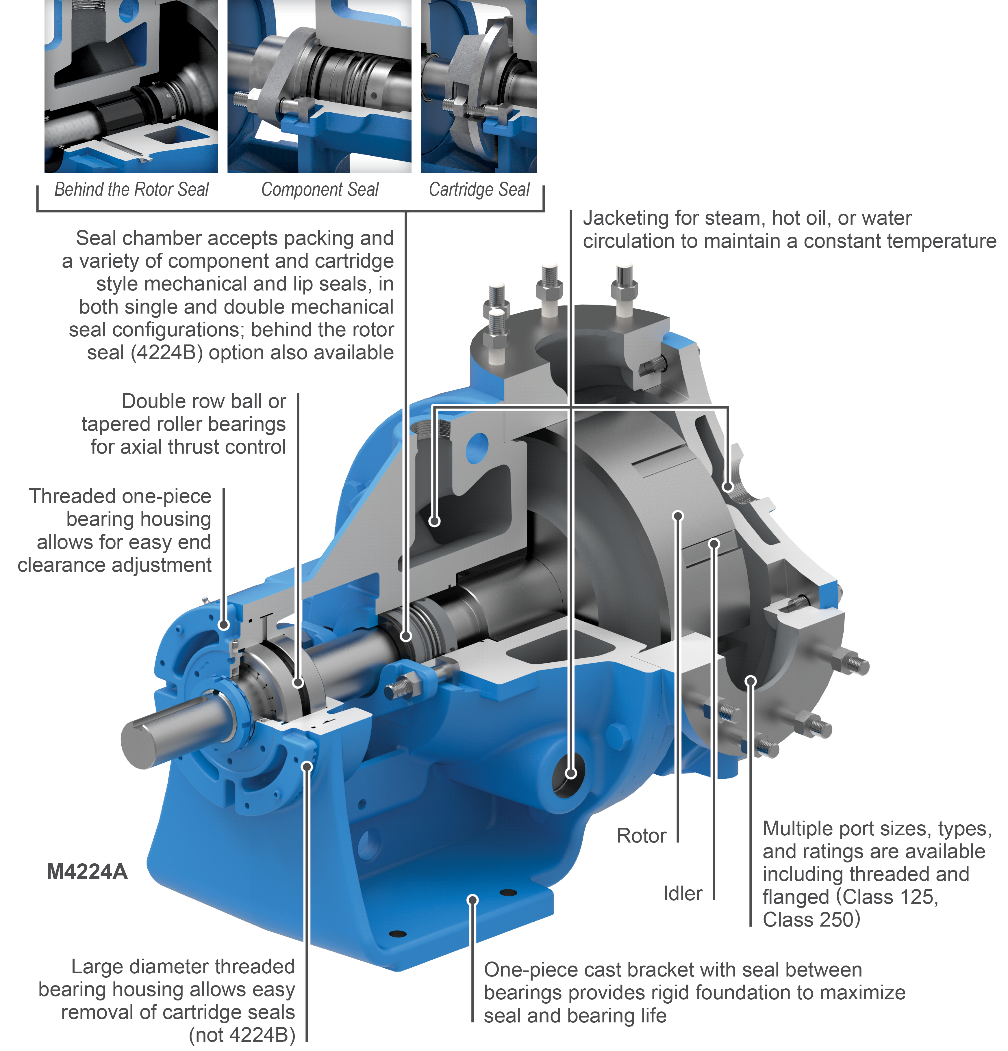
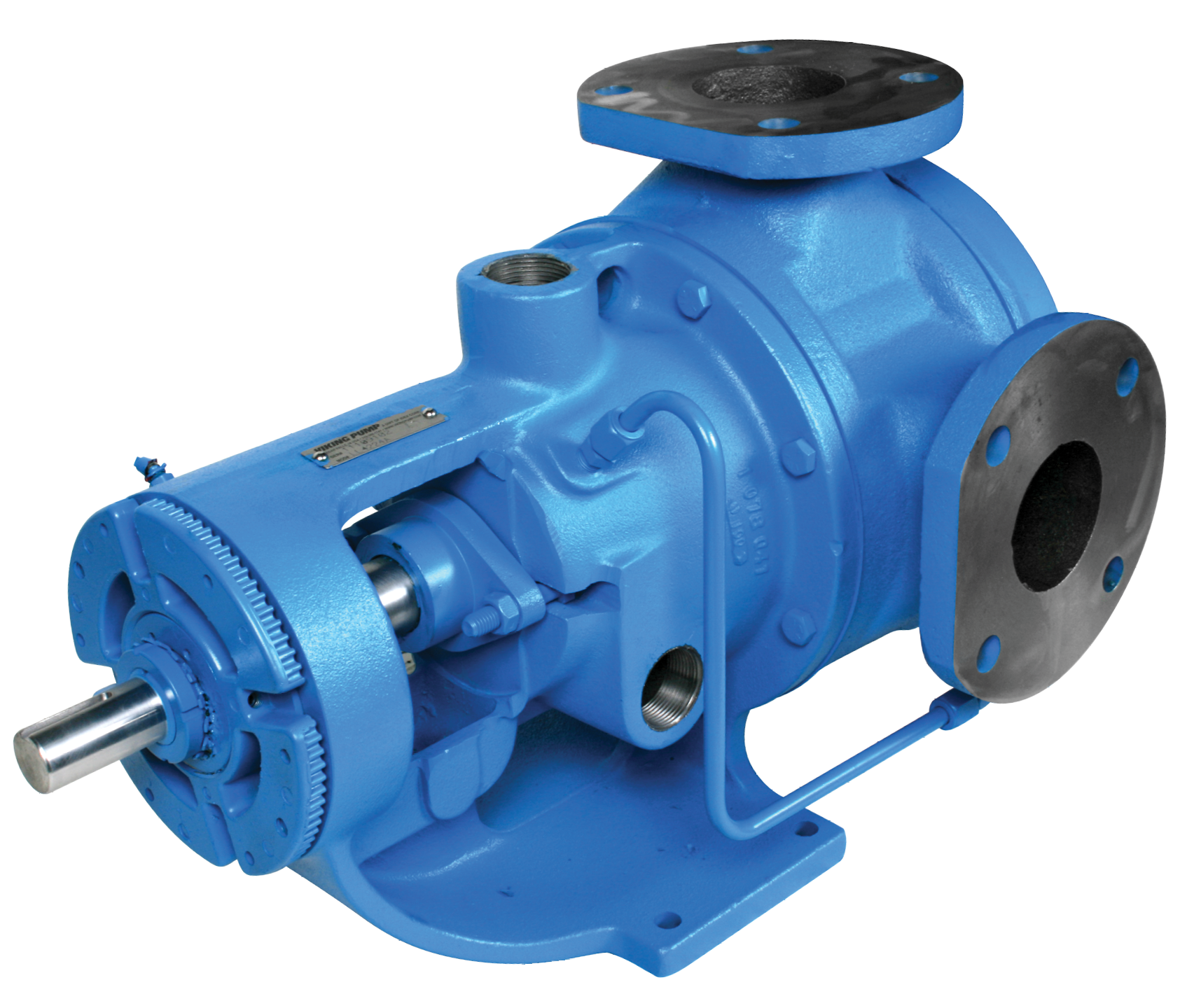
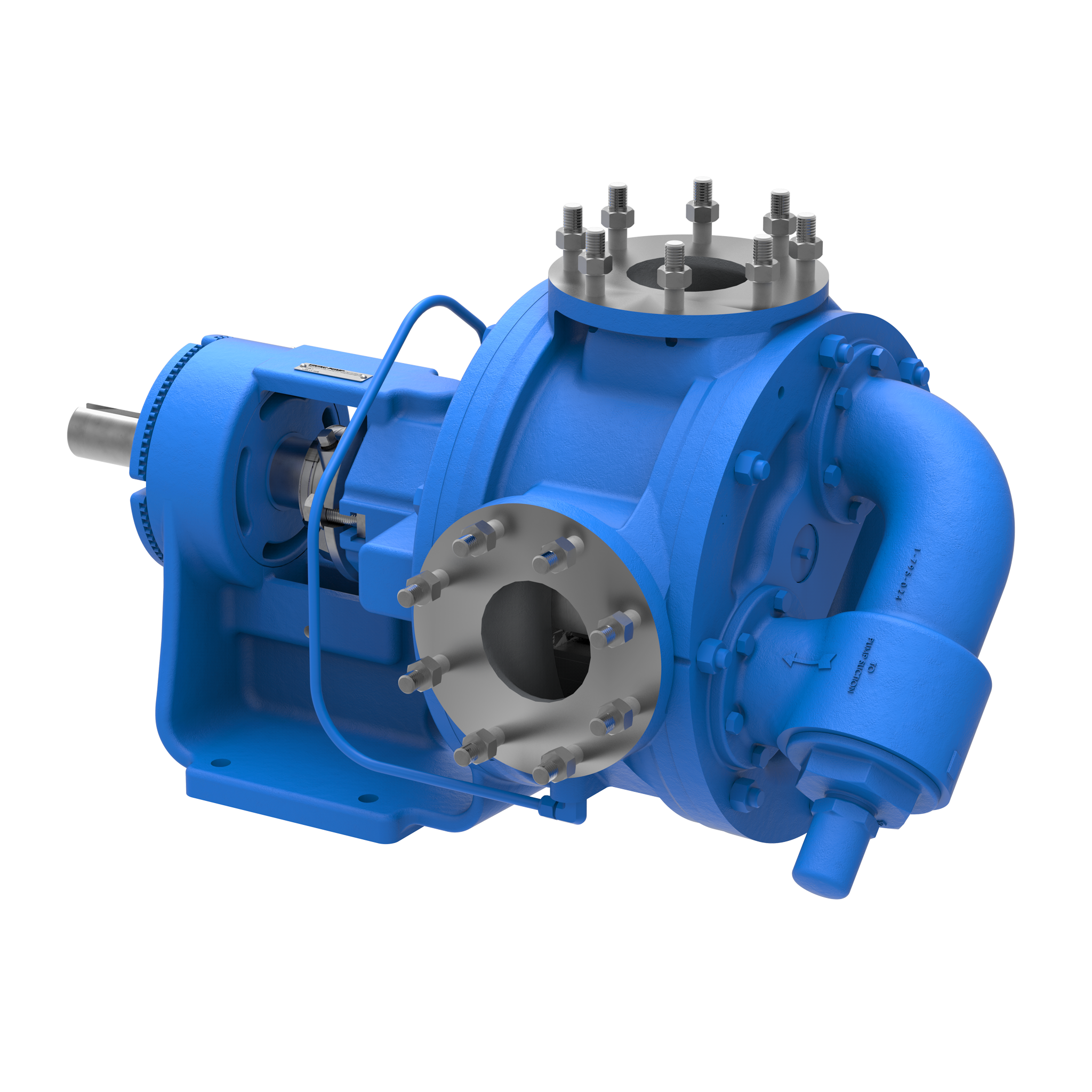
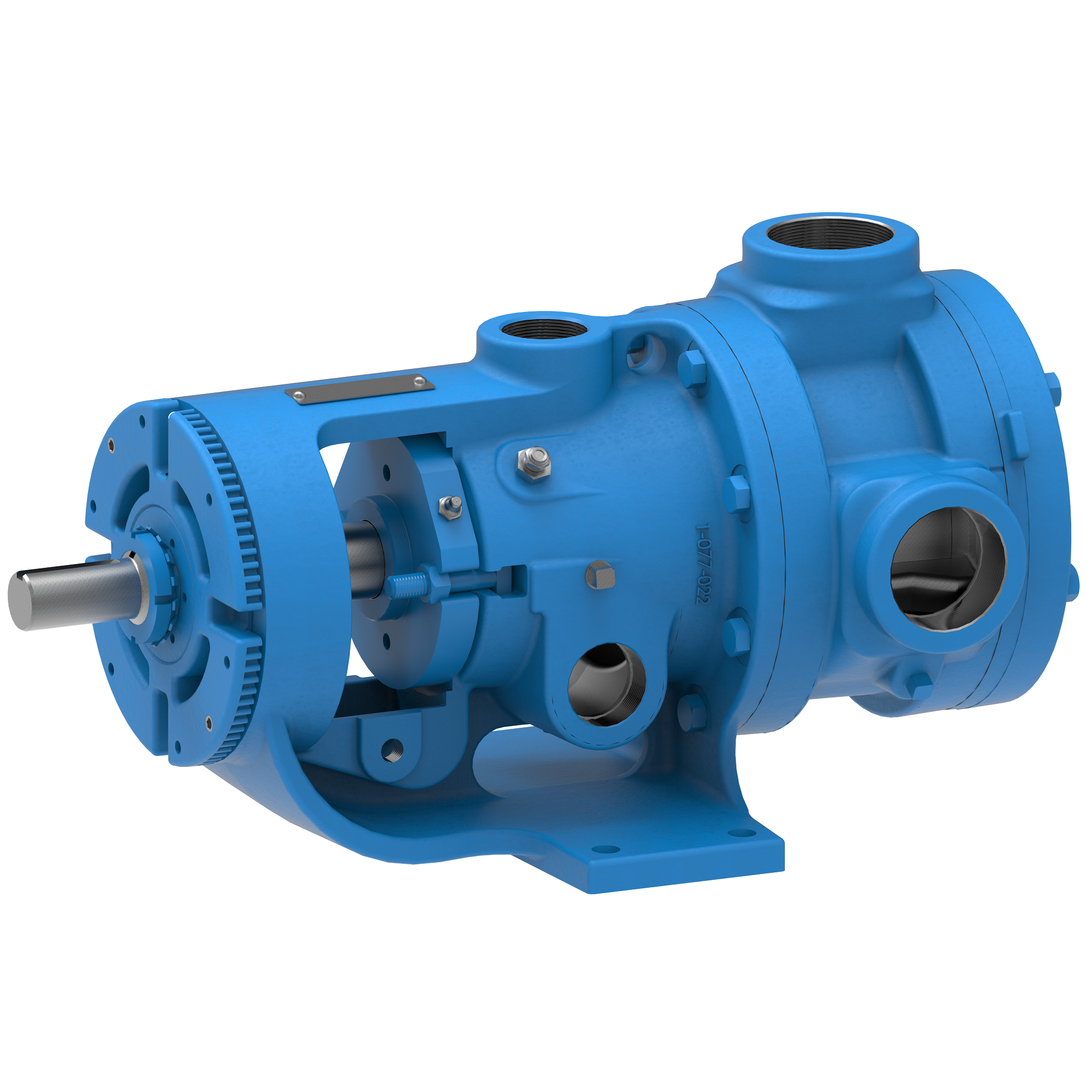
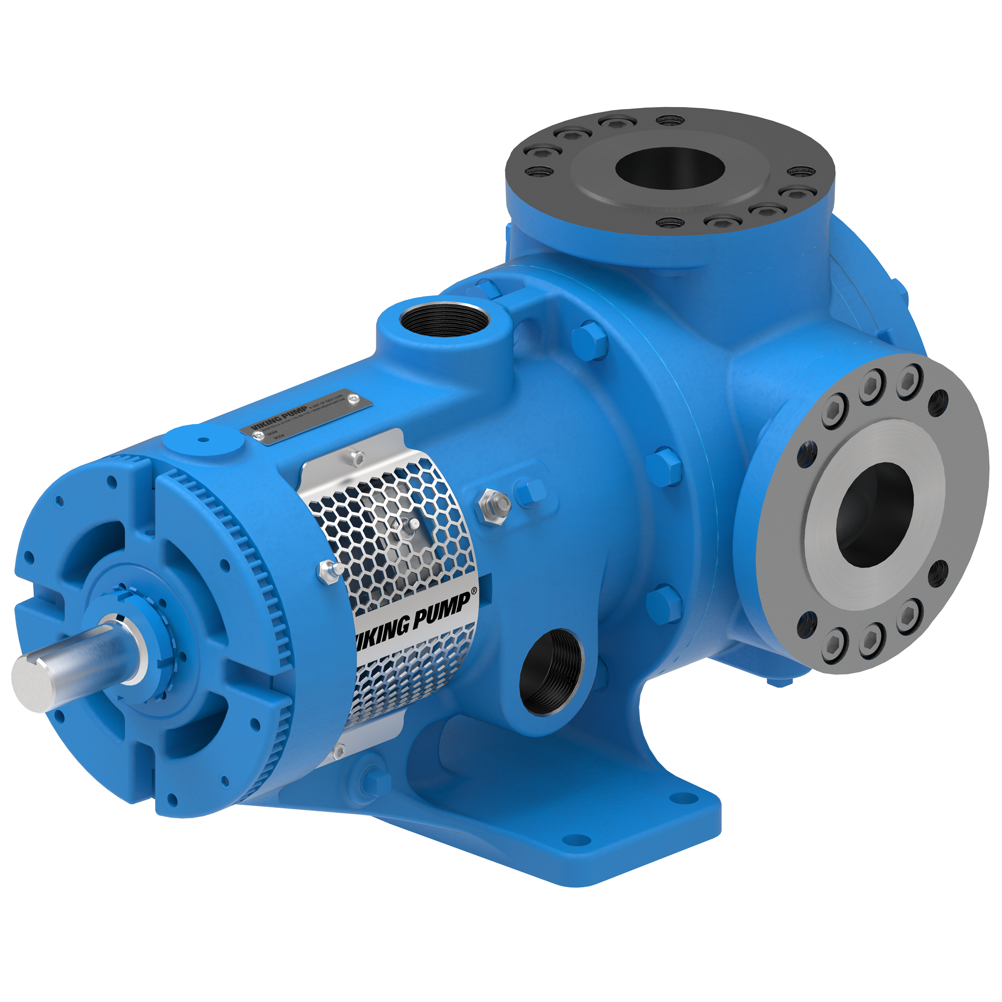
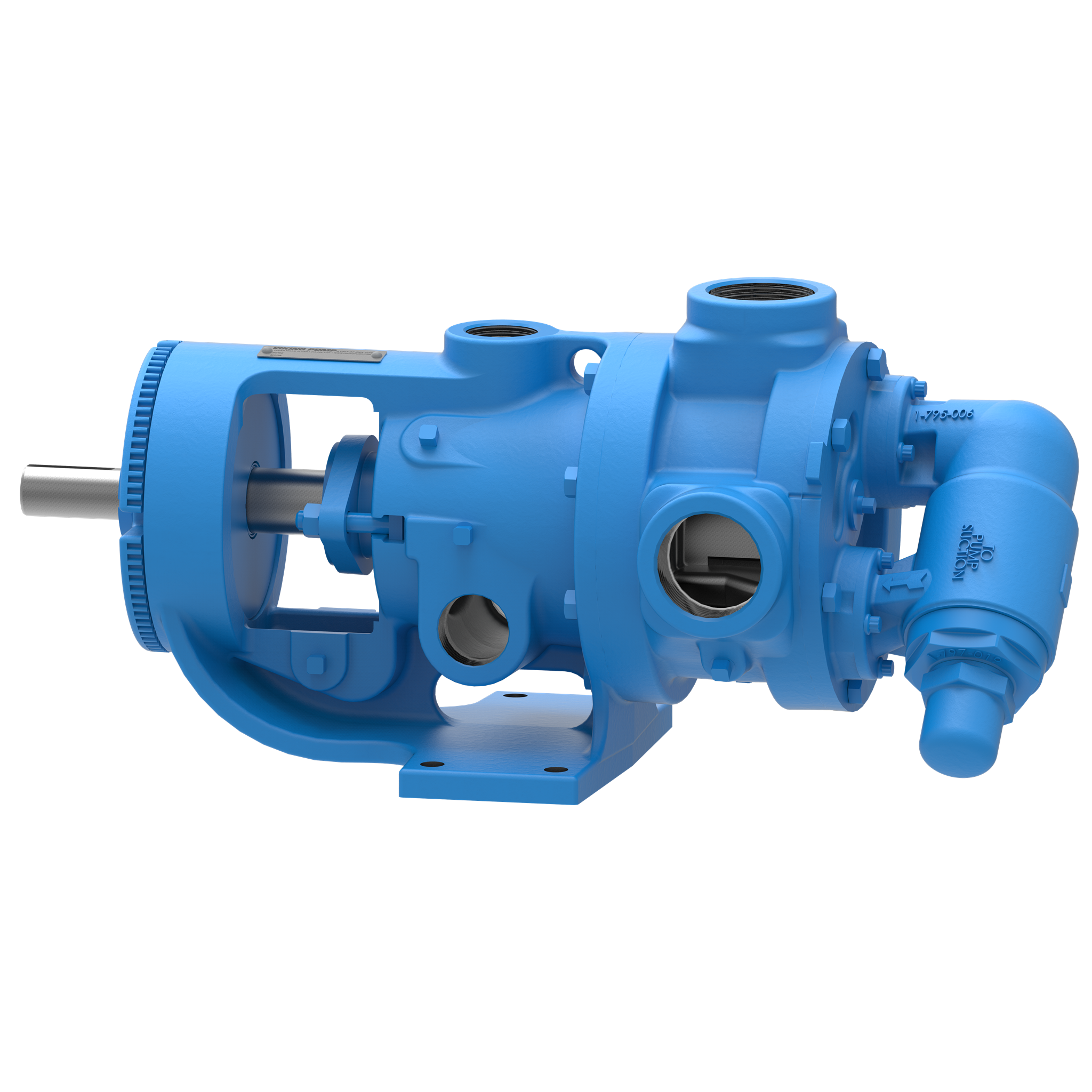
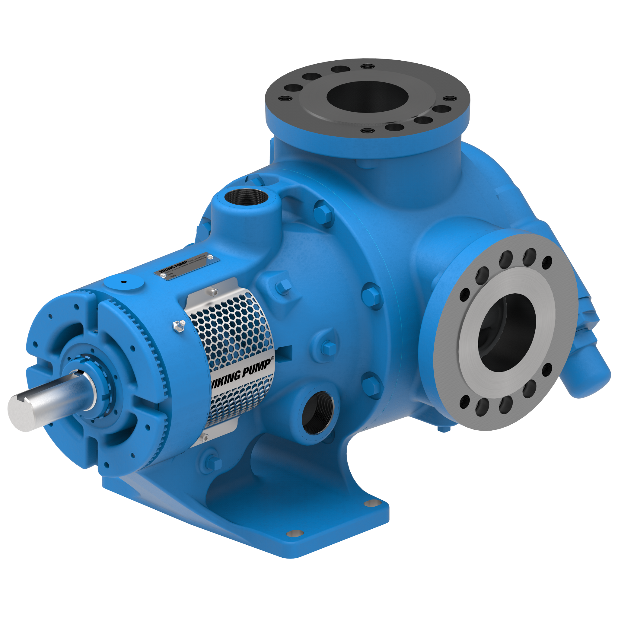
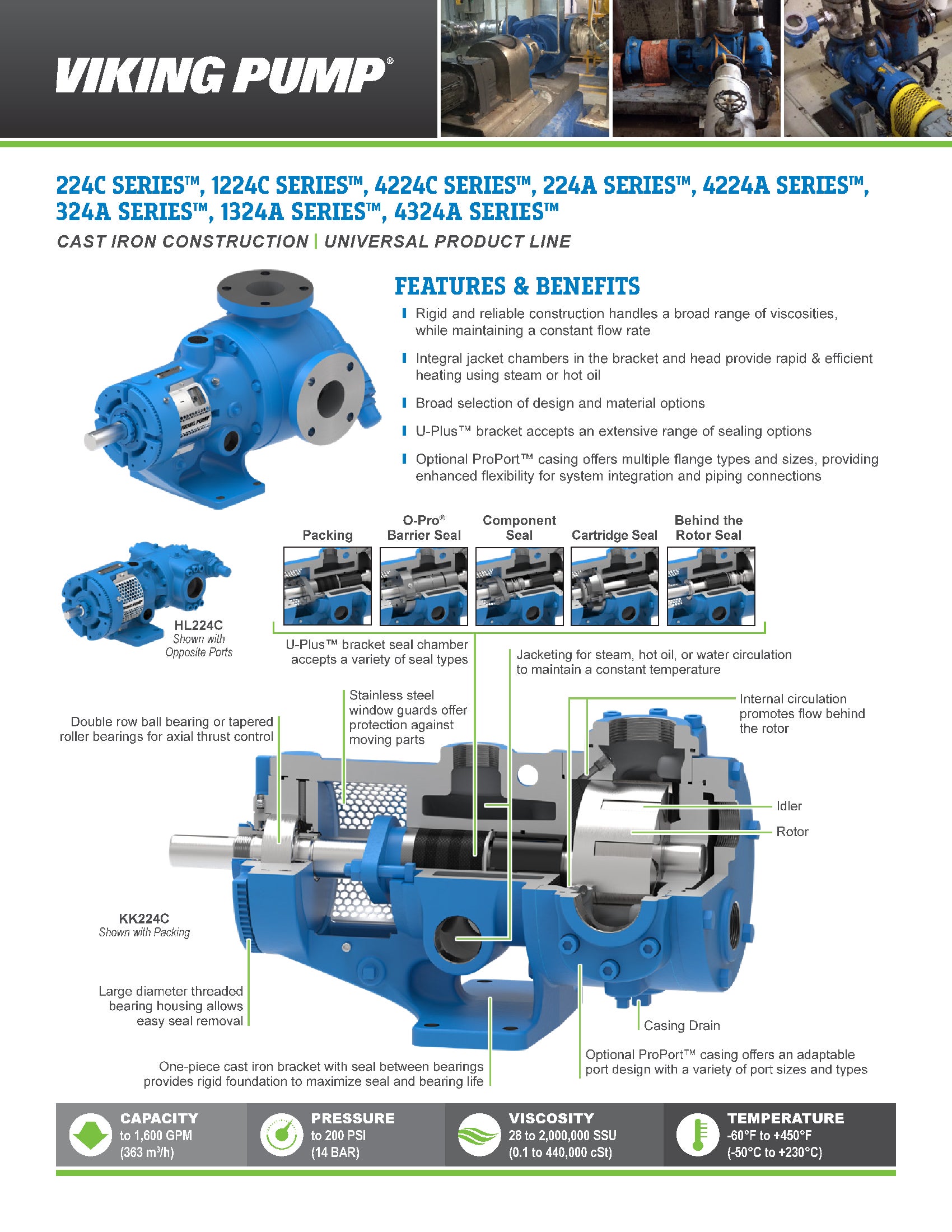
La bomba de engranaje interno 4224A Series™ es la solución ideal para fuelóleo pesado, ceras, soluciones de caucho y otros productos, gracias a su capacidad para calentar de forma rápida y eficiente utilizando vapor o aceite caliente. Puede manejar caudales de hasta 500 GPM (114 m³/h).
Características y ventajas
- Resistente y fiable, pero económico
- La más amplia gama de tamaños y opciones disponibles para adaptarse a casi cualquier aplicación no corrosiva
- Las cámaras de camisa integradas en el soporte y el cabezal rodean la junta y los componentes internos de la bomba para un calentamiento rápido y eficiente mediante vapor o aceite caliente
Photos
Videos


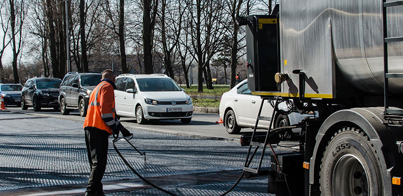
Emulsiones asfálticas
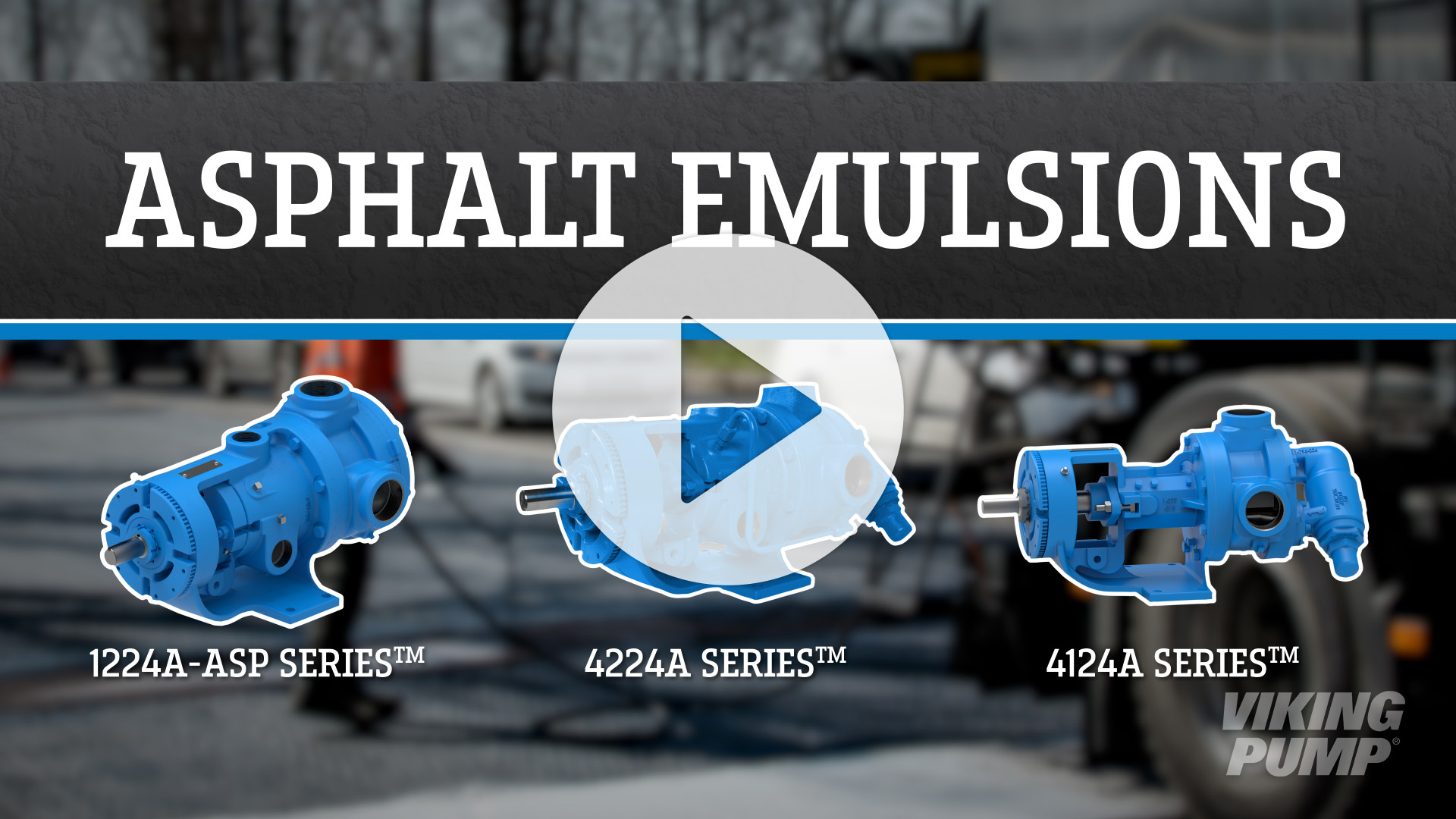
Las emulsiones son asfalto suspendido en una mezcla con agua u otros líquidos. Esto se hace para facilitar la aplicación del asfalto. Los usos serían el relleno de grietas, el revestimiento de carreteras o la impermeabilización. Estas emulsiones son sensibles al cizallamiento y deben manipularse con cuidado.
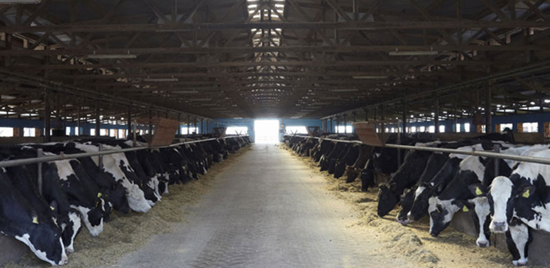
Melaza
La melaza se define como el licor madre almibarado que queda después de haber eliminado la sacarosa del zumo de caña mediante concentración. Si sólo se ha eliminado una cosecha de cristales, se denomina Primera Melaza. Si se ha eliminado la segunda cosecha, el producto se denomina Segunda Melaza, y así sucesivamente. Cuando ya no se puede extraer más azúcar de caña, se denomina Melaza Final o Melaza de Correa Negra.
Cera
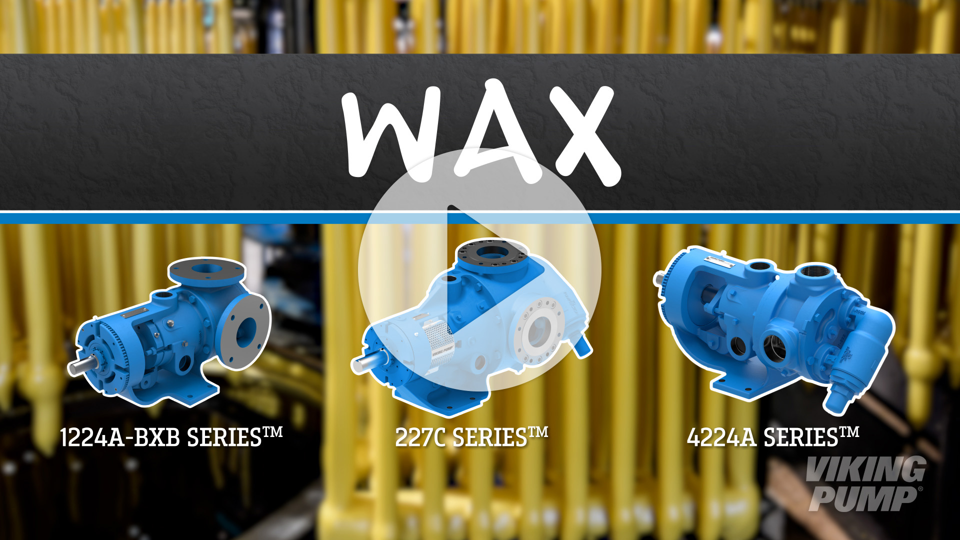
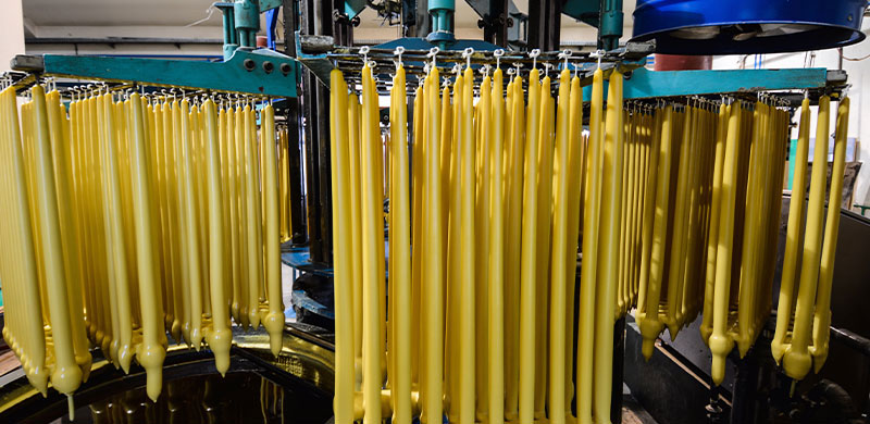
Las ceras pueden ser secreciones naturales de plantas o animales, como la cera de abejas, o subproductos del refinado del petróleo. La cera se utiliza habitualmente en las industrias del papel y el cartón para que productos como los envases de cartón y papel sean resistentes a la humedad. La cera también puede ayudar a evitar que los productos alimenticios se peguen a los envases de papel.
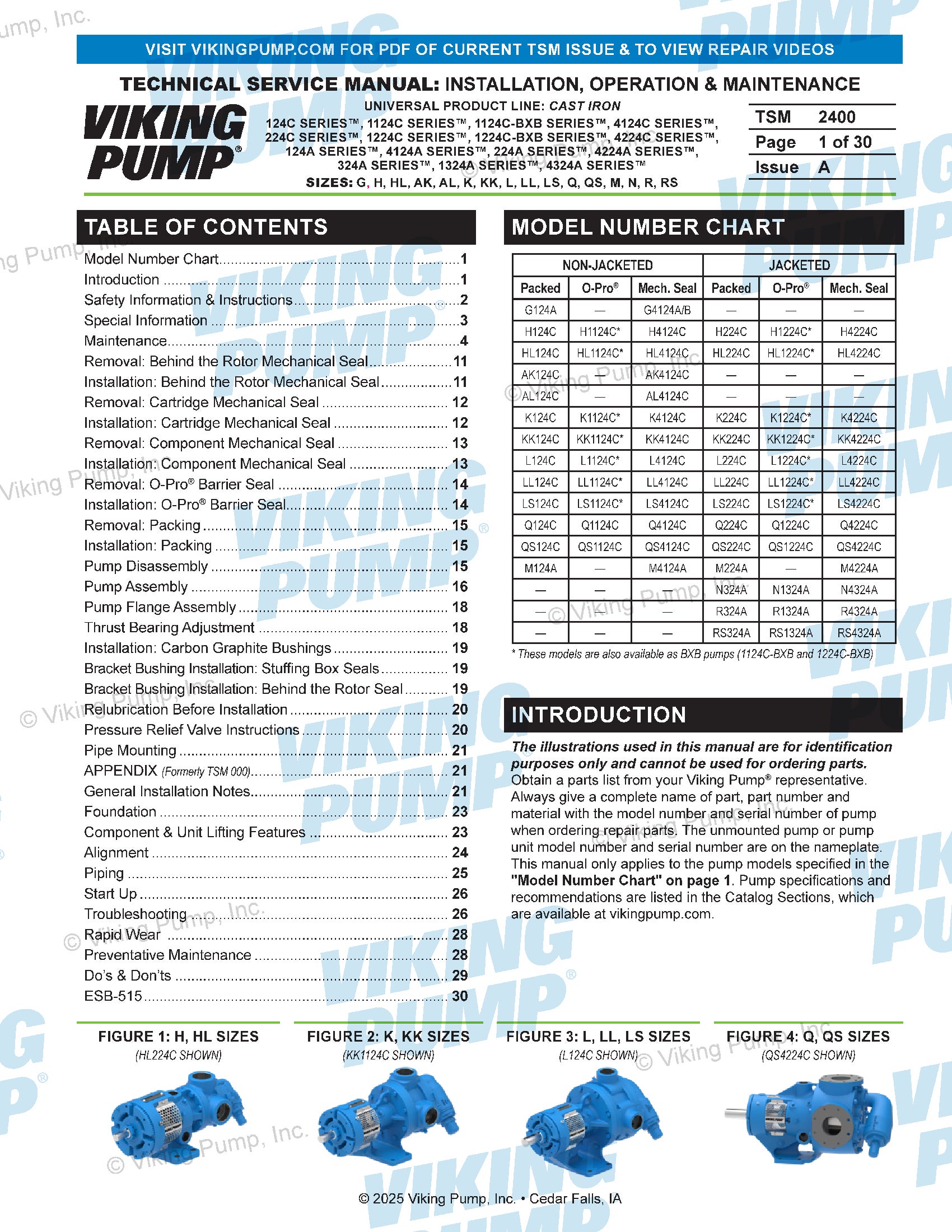
Technical Service Manuals
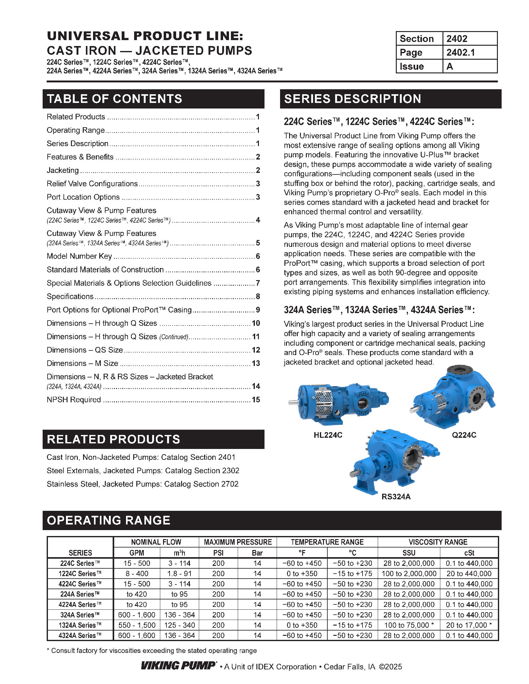
Catalog Sections
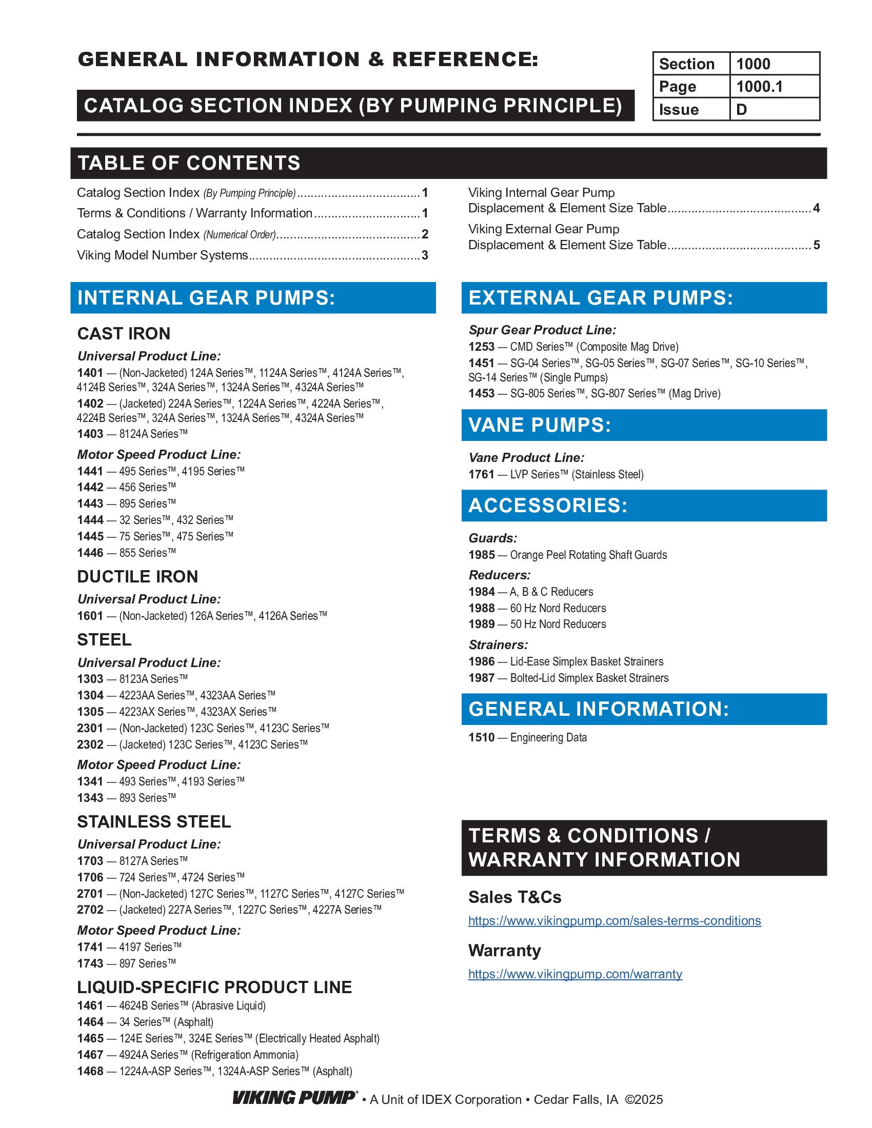
Product Flyers
Product Flyers


-
DRAWINGS

H-HL with Relief Valve - 1.5" Class 125 ANSI RH/LH  PDF
PDF
H-HL with Relief Valve - 1.5" NPT RH
PDF
 STEP
STEP
K-KK with Plain Head - 2" NPT RH/LH
PDF
STEP
K-KK with Plain Head - 3" Class 125 ANSI RH
PDF
STEP
K-KK with Relief Valve - 2" NPT RH
PDF
STEP
L with Jacketed Relief Valve - 2" NPT RH
PDF
STEP
L with Jacketed Relief Valve - 3" Class 125 ANSI RH
PDF
STEP
L with Plain Head - 2" NPT RH
PDF
STEP
L with Relief Valve - 2" NPT RH/LH
PDF
STEP
LL with Jacketed Relief Valve - 3" Class 125 ANSI RH
PDF
STEP
LL with Plain Head - 3" Class 125 ANSI RH/LH
PDF
STEP
LL with Relief Valve - 3" Class 125 ANSI RH/LH
PDF
STEP
LQ with Jacketed Relief Valve - 2.5" Class 125 ANSI RH
PDF
STEP
LQ with Plain Head - 2.5" Class 125 ANSI RH/LH
PDF
STEP
LQ with Relief Valve - 2.5" Class 125 ANSI RH/LH
PDF
STEP
LS with Plain Head - 3" Class 125 ANSI RH/LH
PDF
STEP
LS with Relief Valve - 3" Class 125 ANSI RH/LH
PDF
STEP
M with Jacketed Relief Valve - 4" Class 125 ANSI RH
PDF
STEP
M with Plain Head - 4" Class 125 ANSI RH
PDF
STEP
M with Relief Valve - 4" Class 125 ANSI RH
PDF
STEP
Q with Jacketed Head - 4" Class 125 ANSI RH/LH
PDF
STEP
Q with Jacketed Relief Valve - 4" Class 125 ANSI RH
PDF
STEP
Q with Relief Valve - 4" Class 125 ANSI RH/LH
PDF
STEP
QS with Jacketed Head - 6" Class 125 ANSI Opposite
PDF
STEP
QS with Jacketed Relief Valve - 6" Class 125 ANSI Opposite
PDF
STEP
QS with Relief Valve - 6" Class 125 ANSI Opposite
PDF
STEP