 United Kingdom
 France
 Italy
Italy
 Germany
 Sweden
 Spain
Spain
 Canada
 India
India


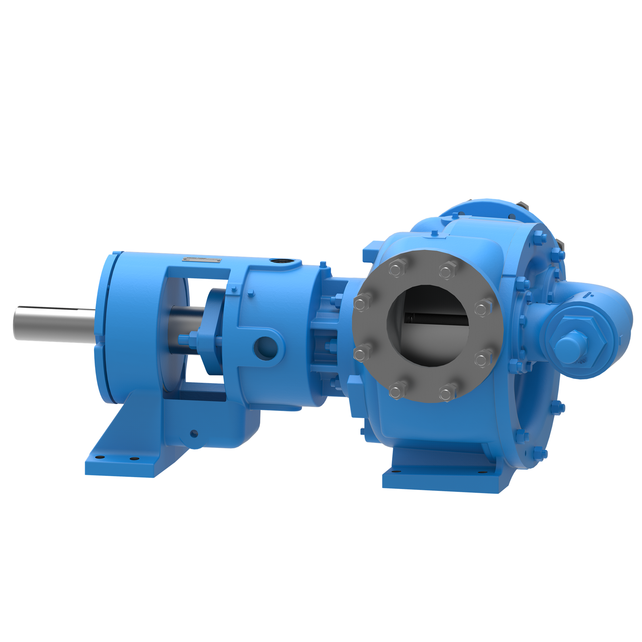
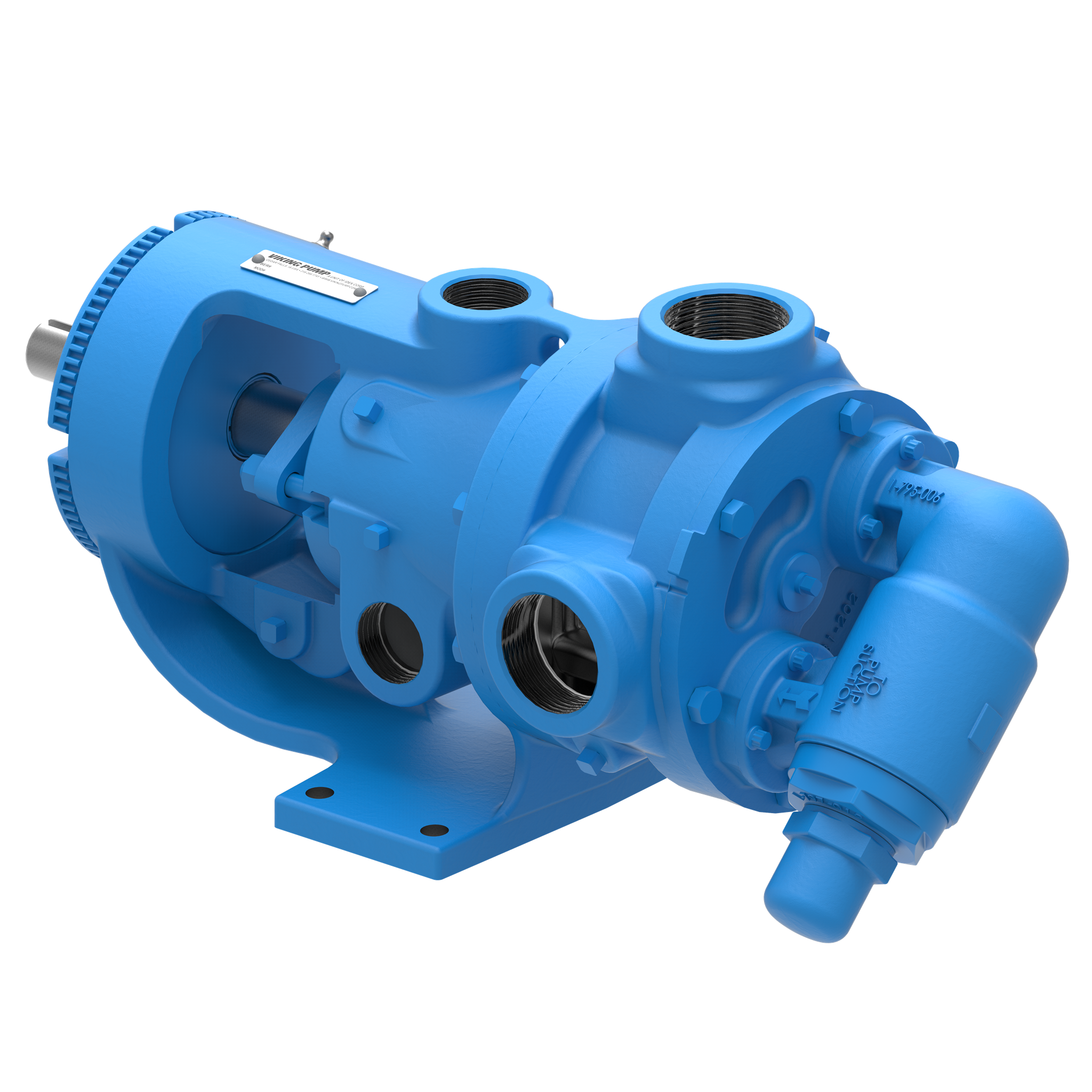
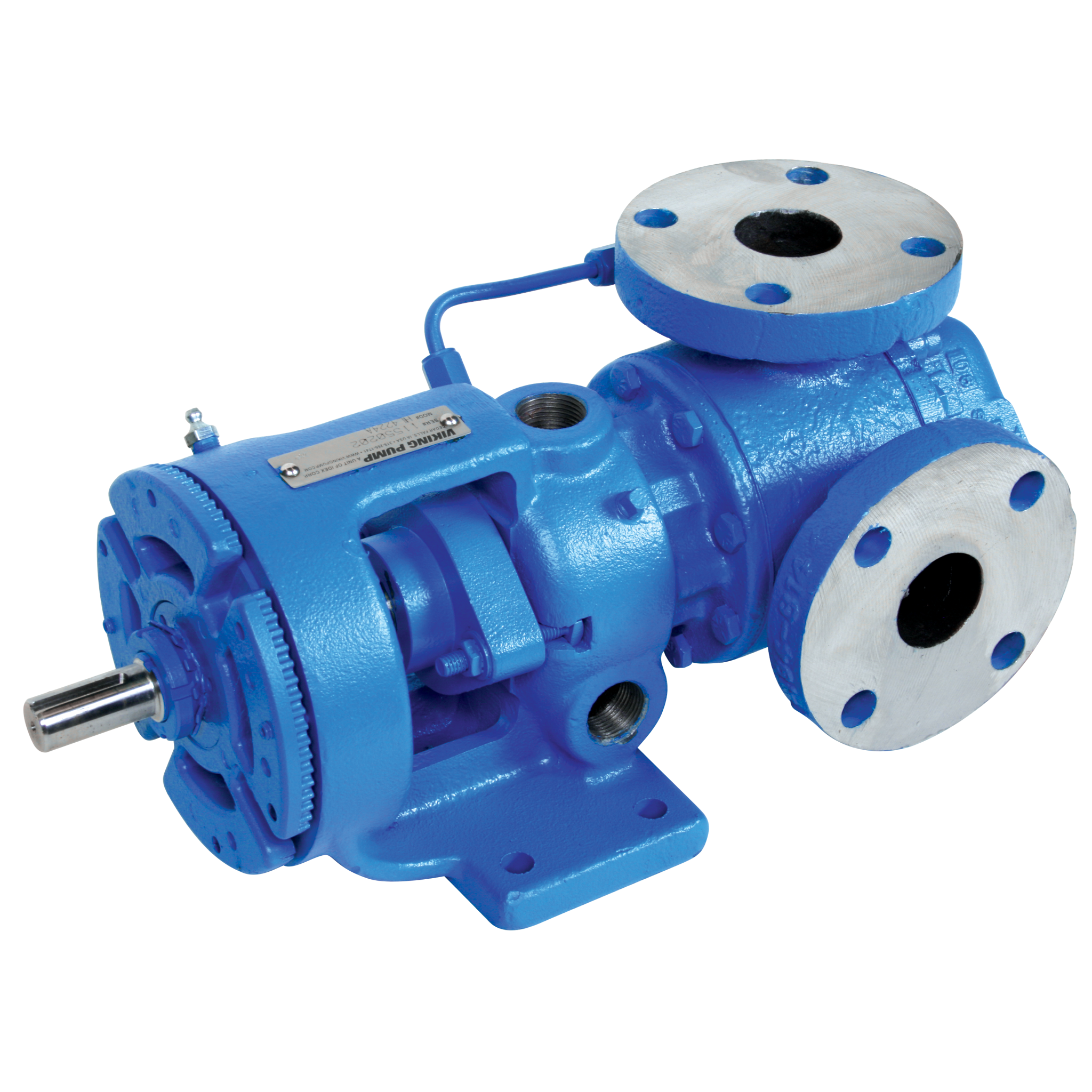
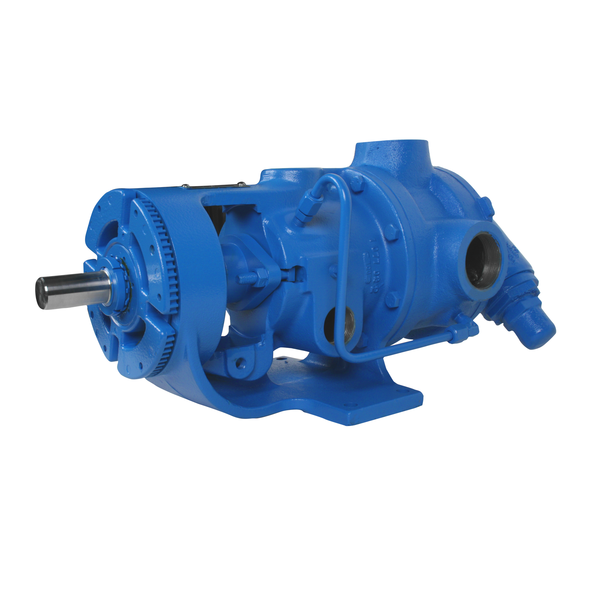
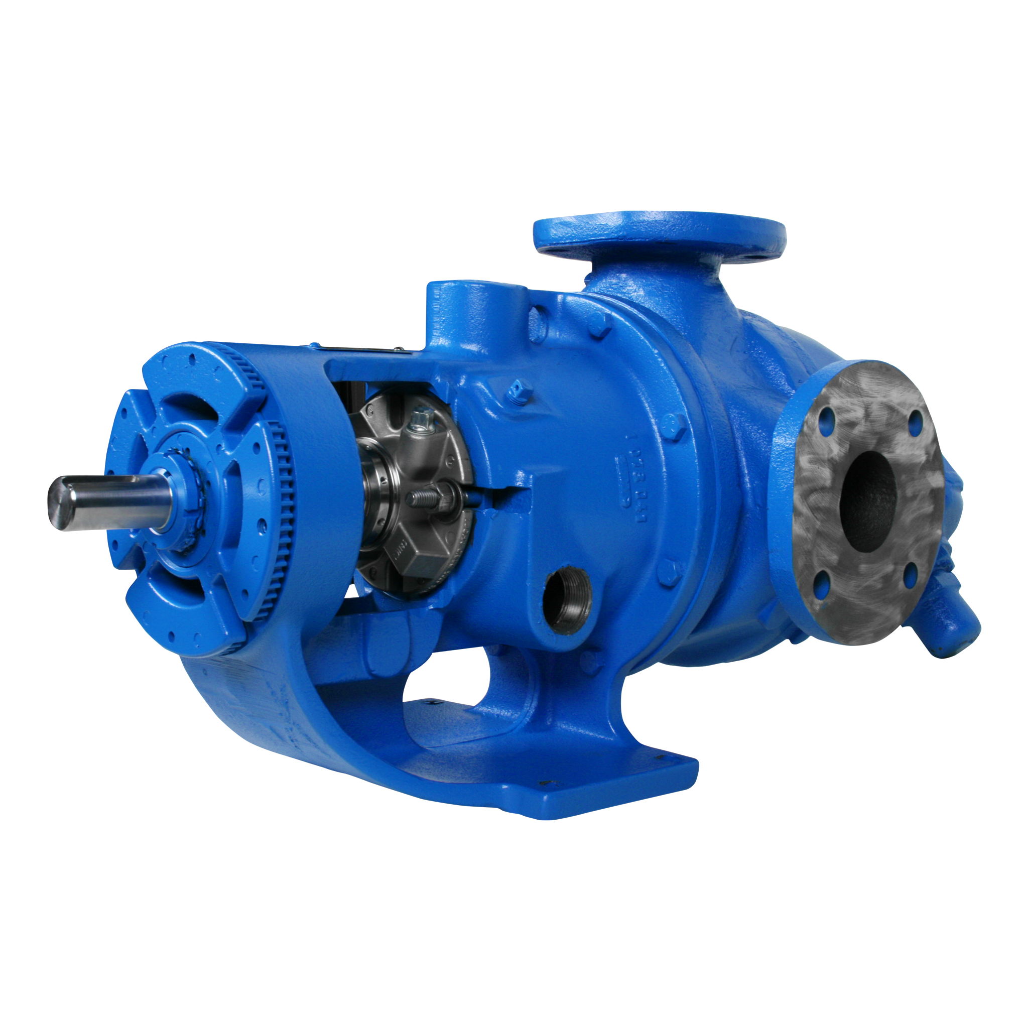
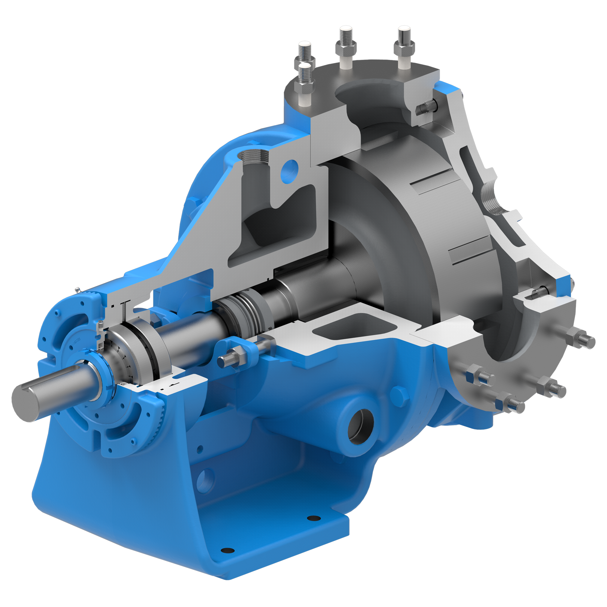
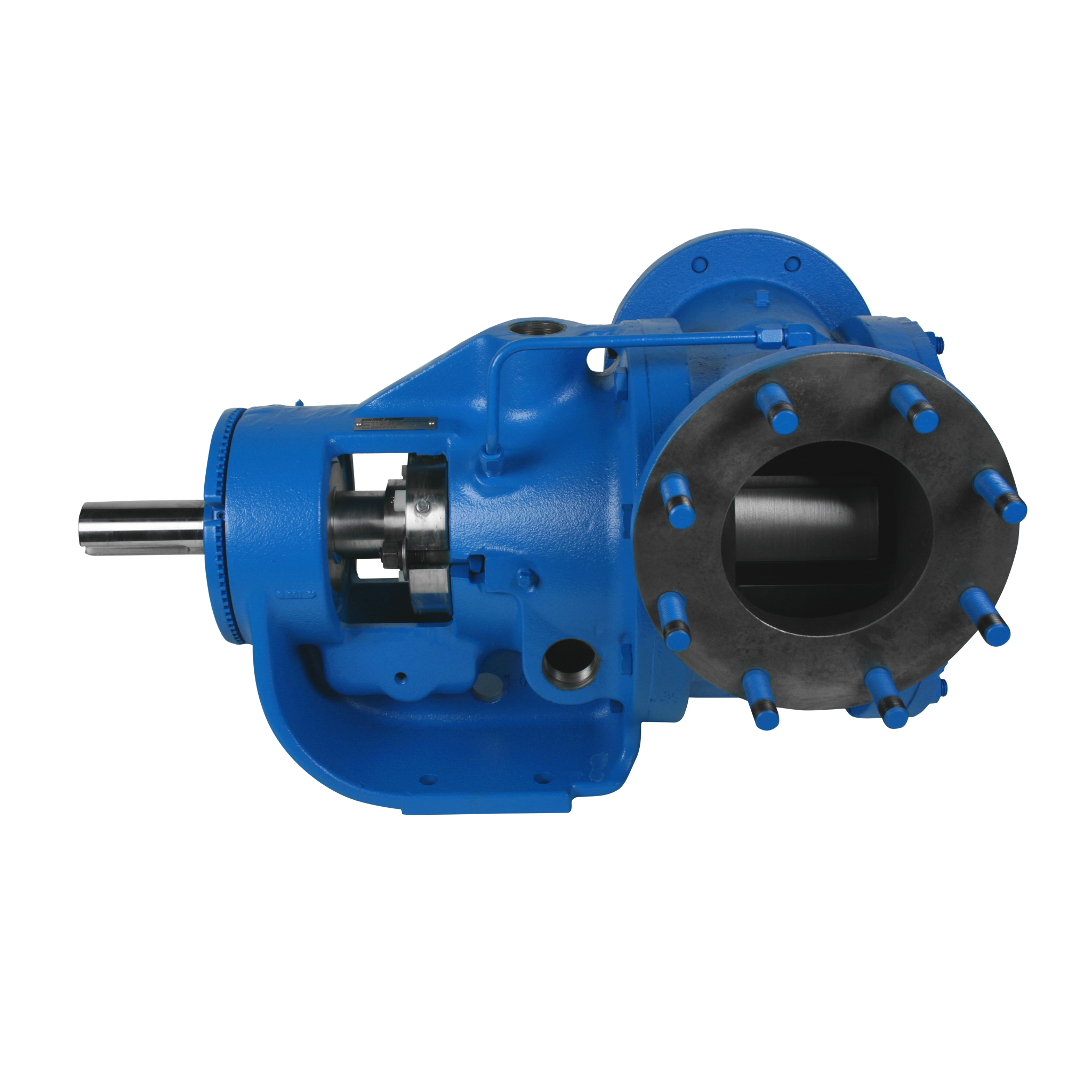
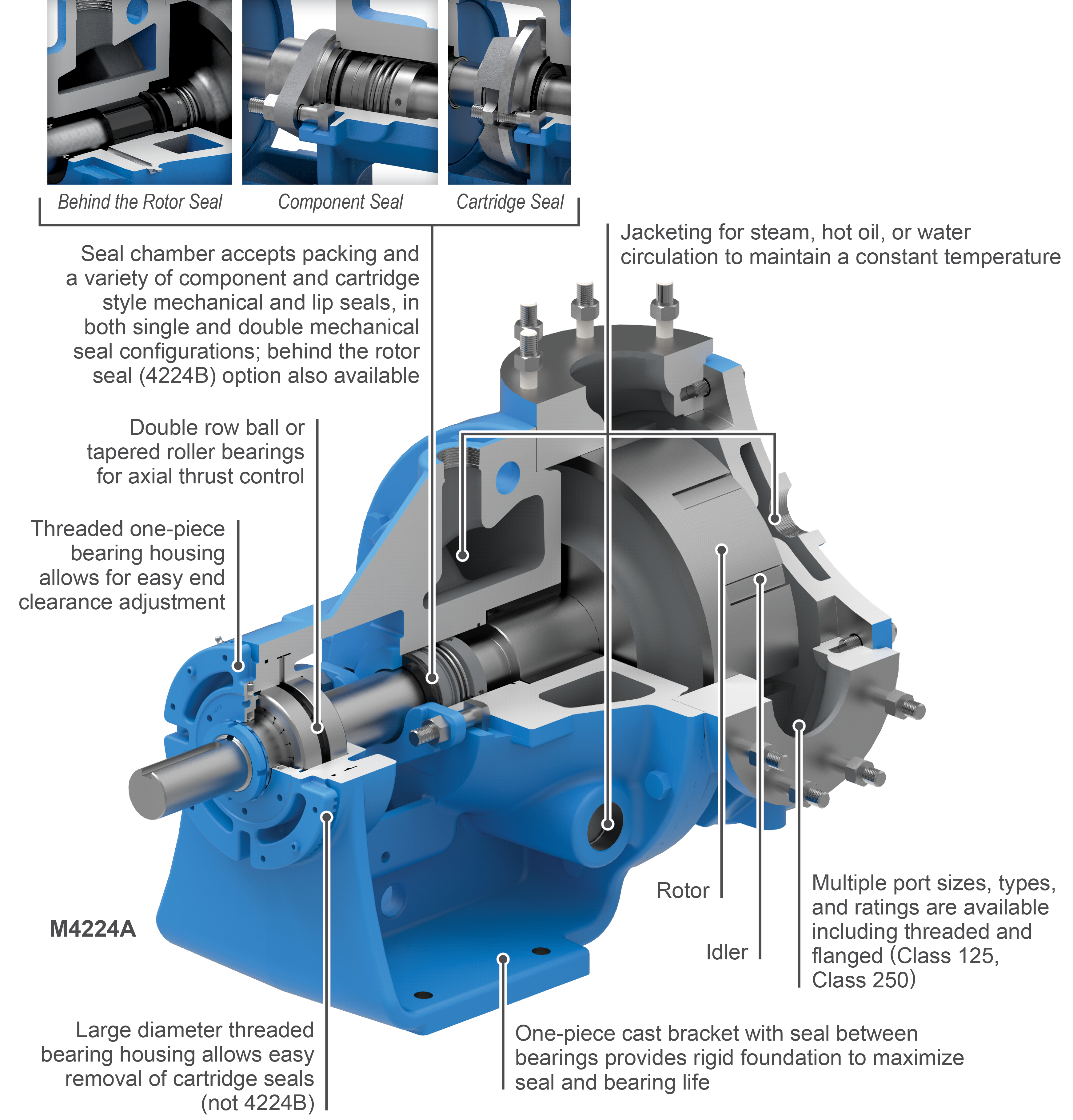
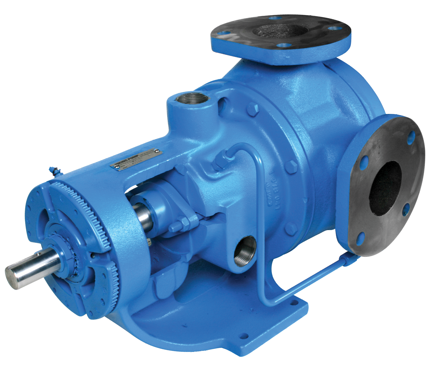
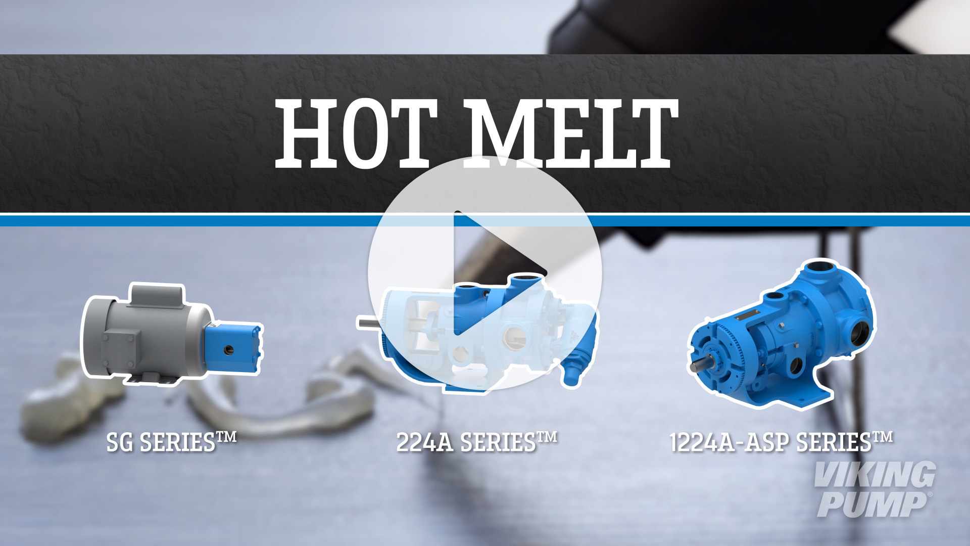
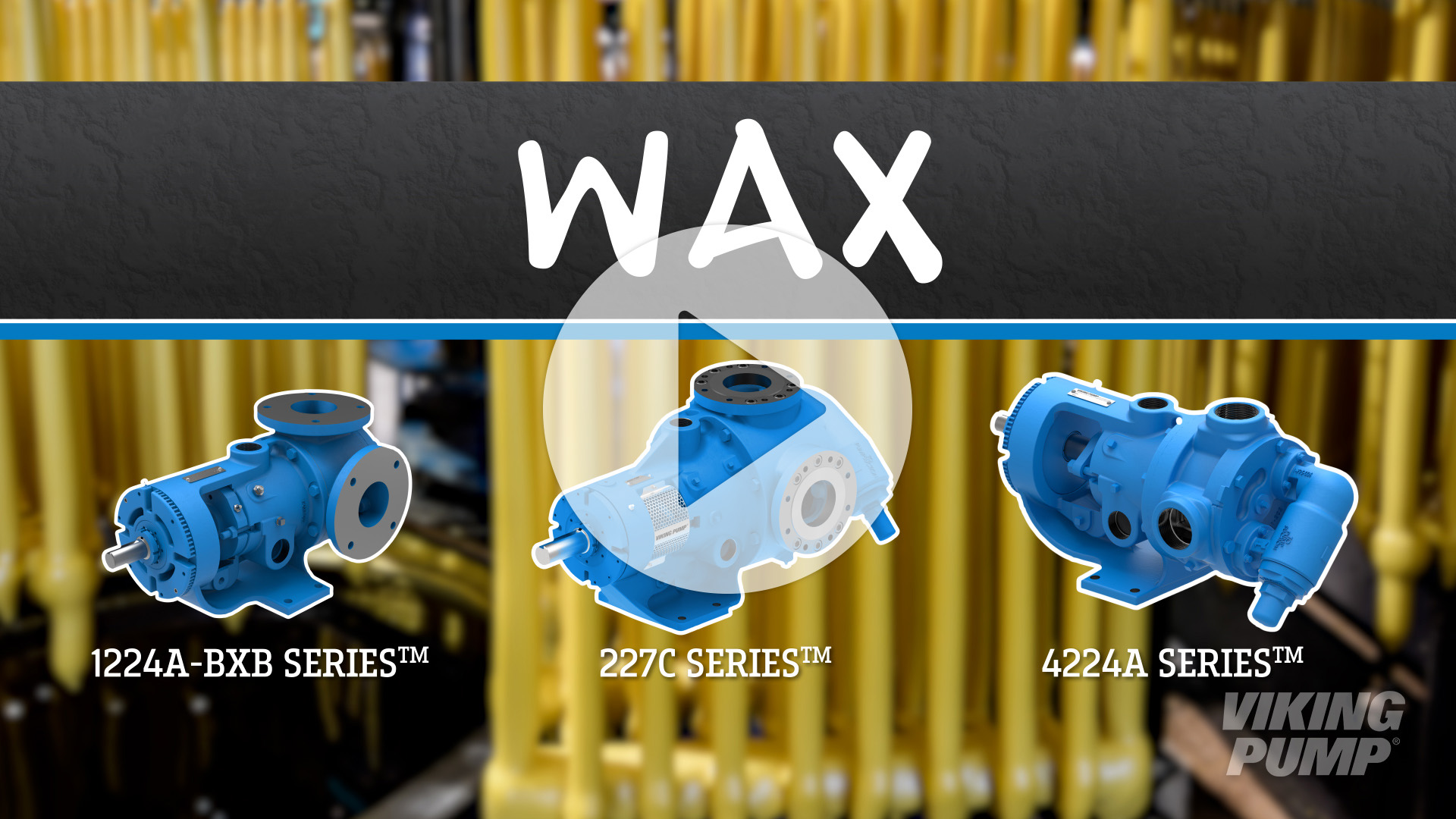
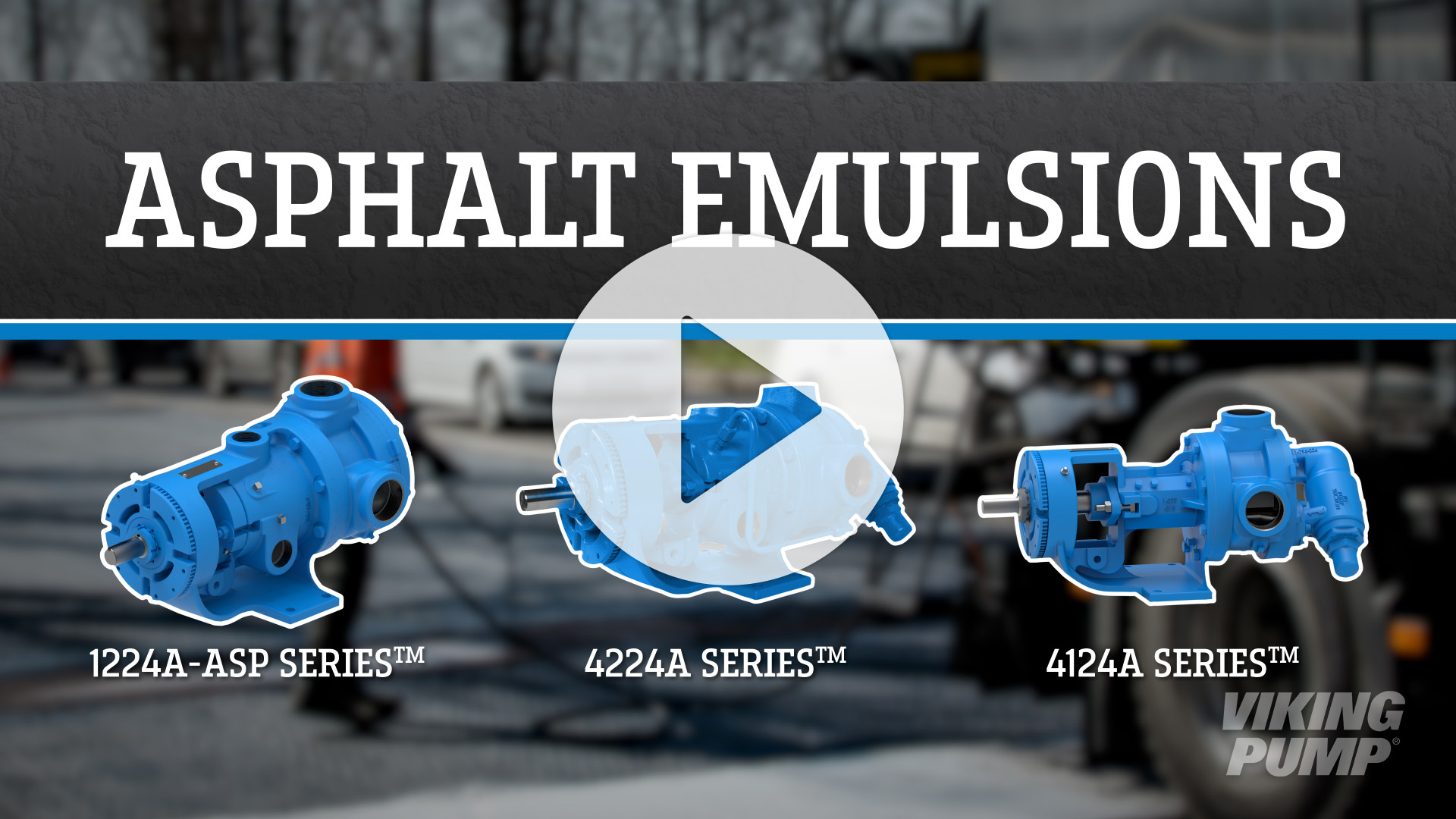
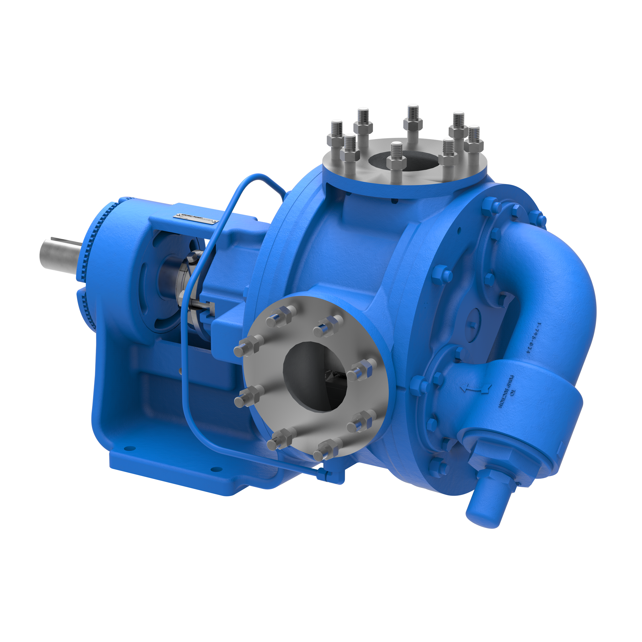
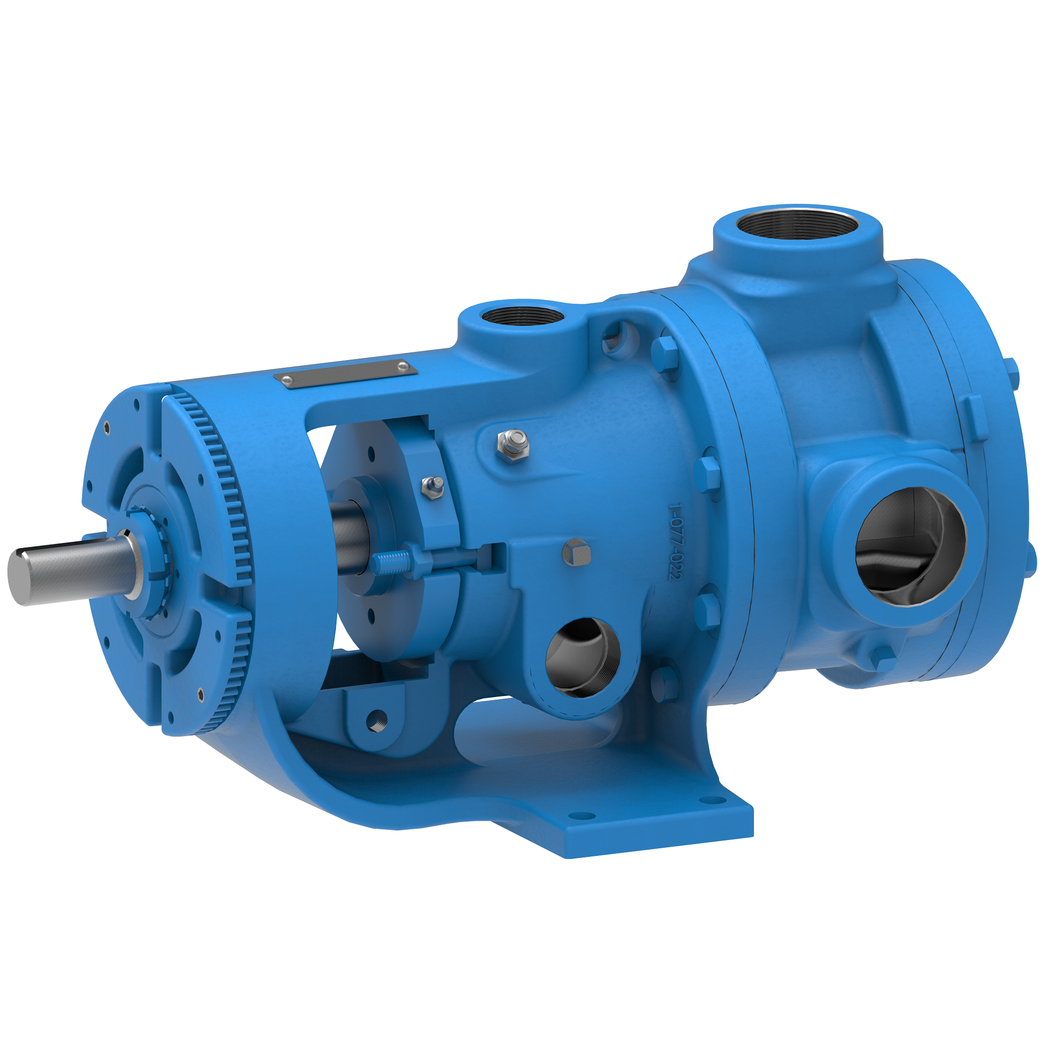
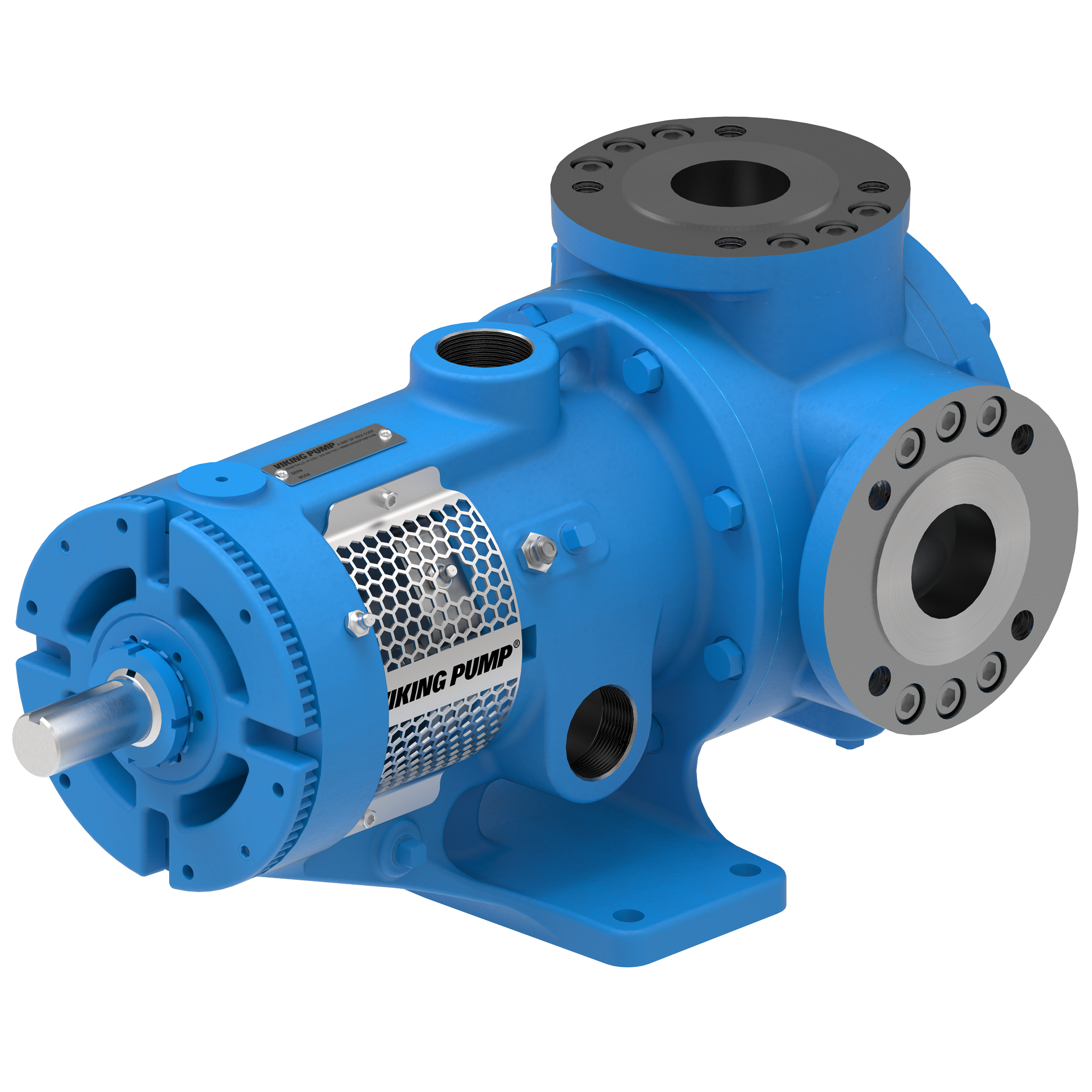
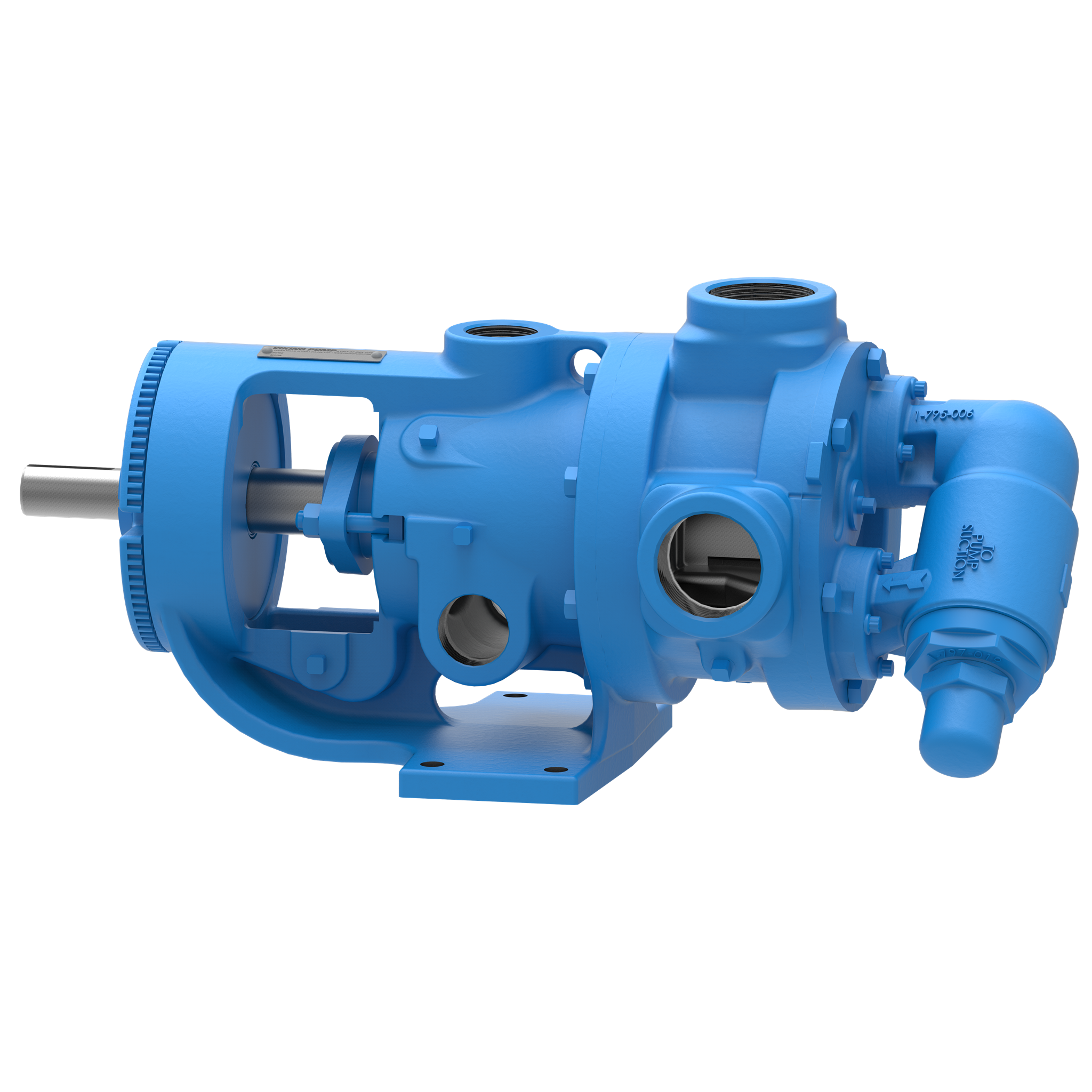
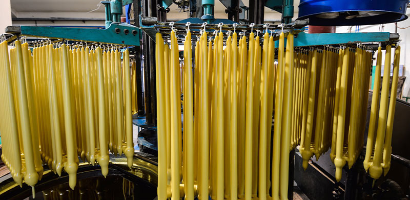
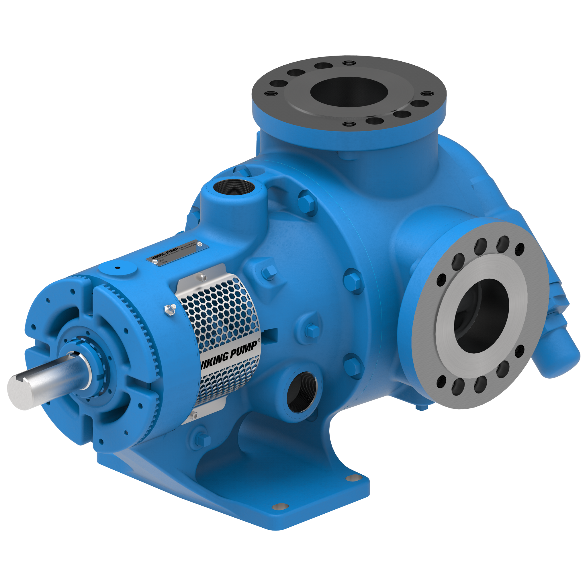
La pompa a ingranaggi interni serie 4224A™ è la soluzione ideale per olio combustibile pesante, cere, soluzioni di gomma e altro ancora grazie alla sua capacità di riscaldarsi rapidamente ed efficacemente utilizzando vapore o olio caldo. È in grado di gestire portate fino a 500 GPM (114 m³/h).
Caratteristiche e Vantaggi
- Robusto e affidabile, ma economico
- Ampia gamma di dimensioni e opzioni disponibili per adattarsi a quasi tutte le applicazioni non corrosive
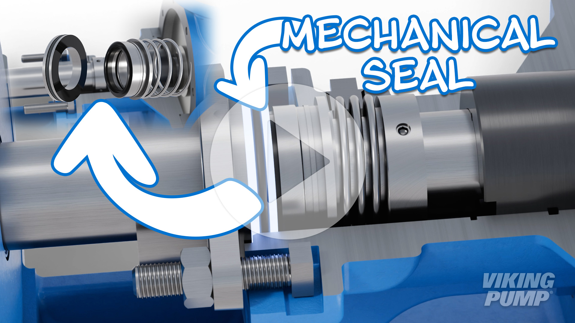
- Le camere di rivestimento integrate nella staffa e nella testa circondano la guarnizione e le parti interne della pompa per un riscaldamento rapido ed efficiente utilizzando vapore o olio caldo
Photos
Videos



TSM / Catalog / Flyers / Brochures
Service Manual | 2400
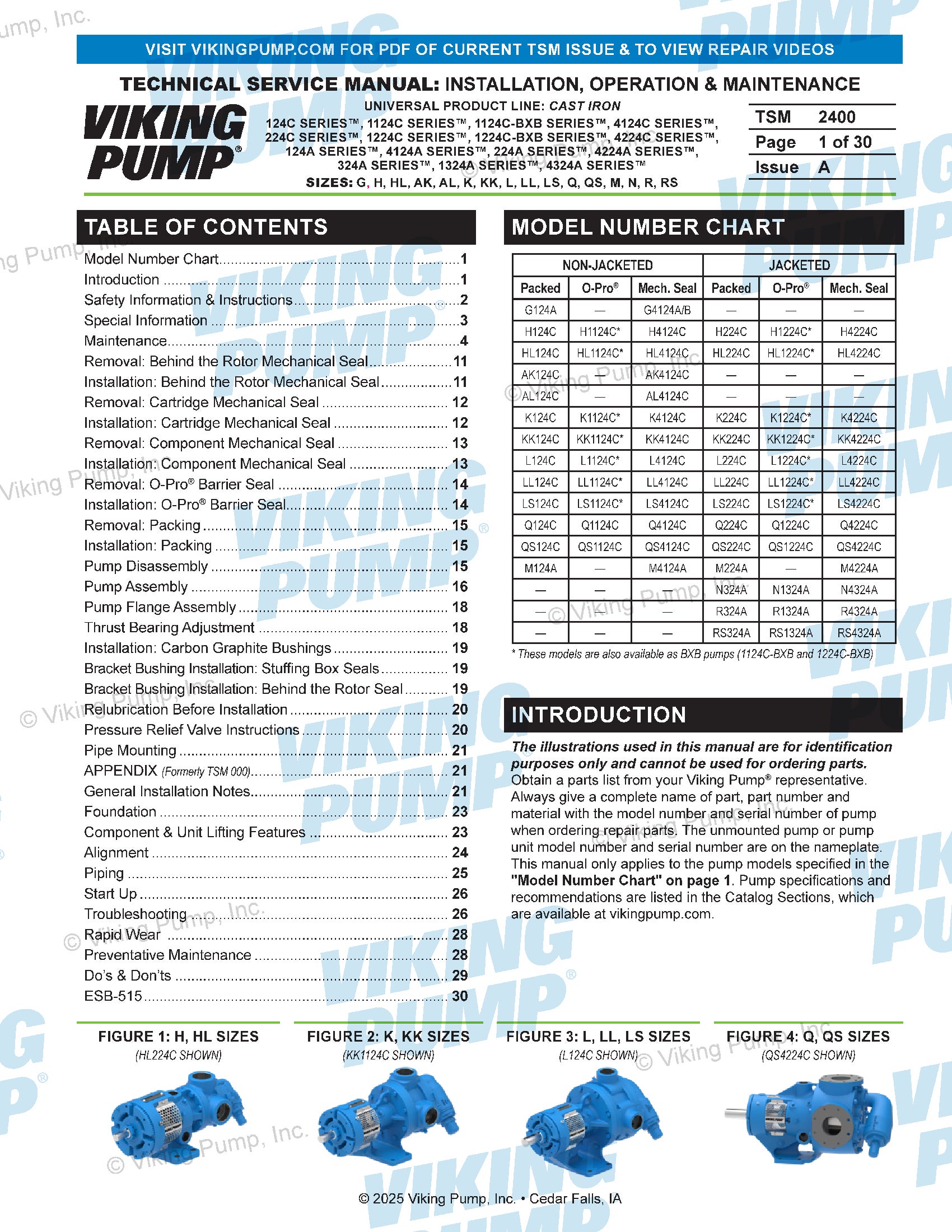
Technical Service Manuals
Catalog Section | 2402 | Jacketed
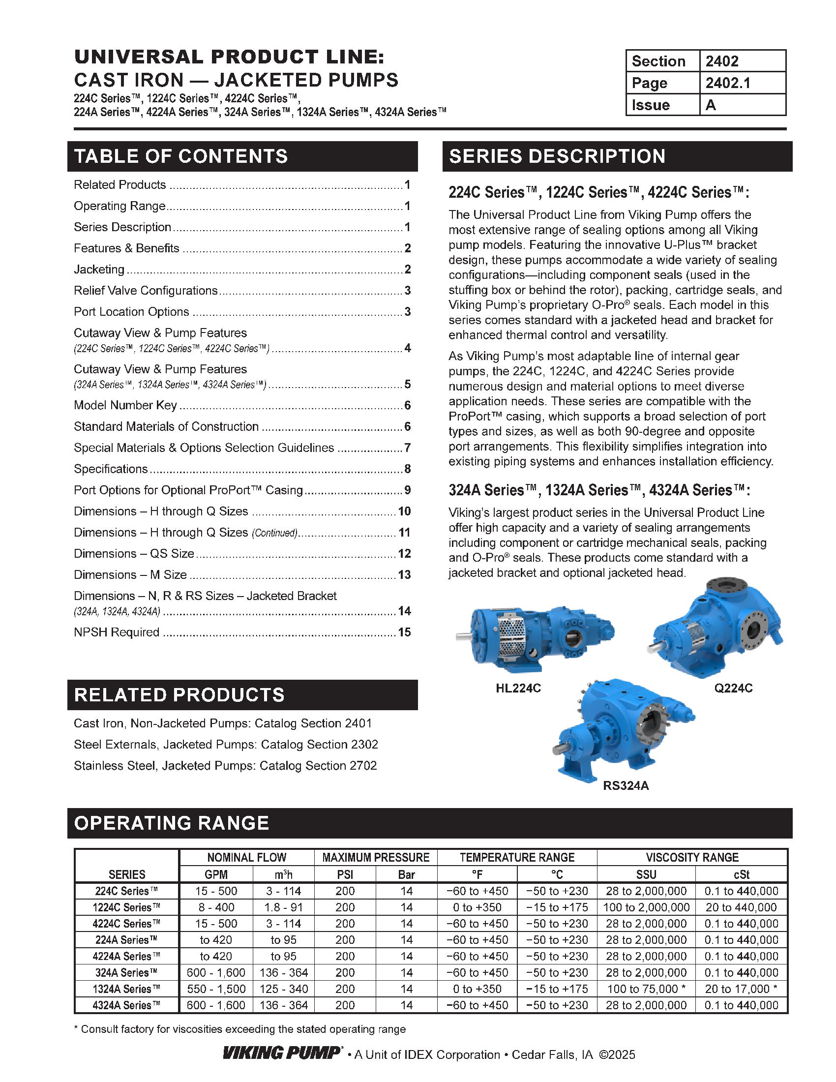
Catalog Sections
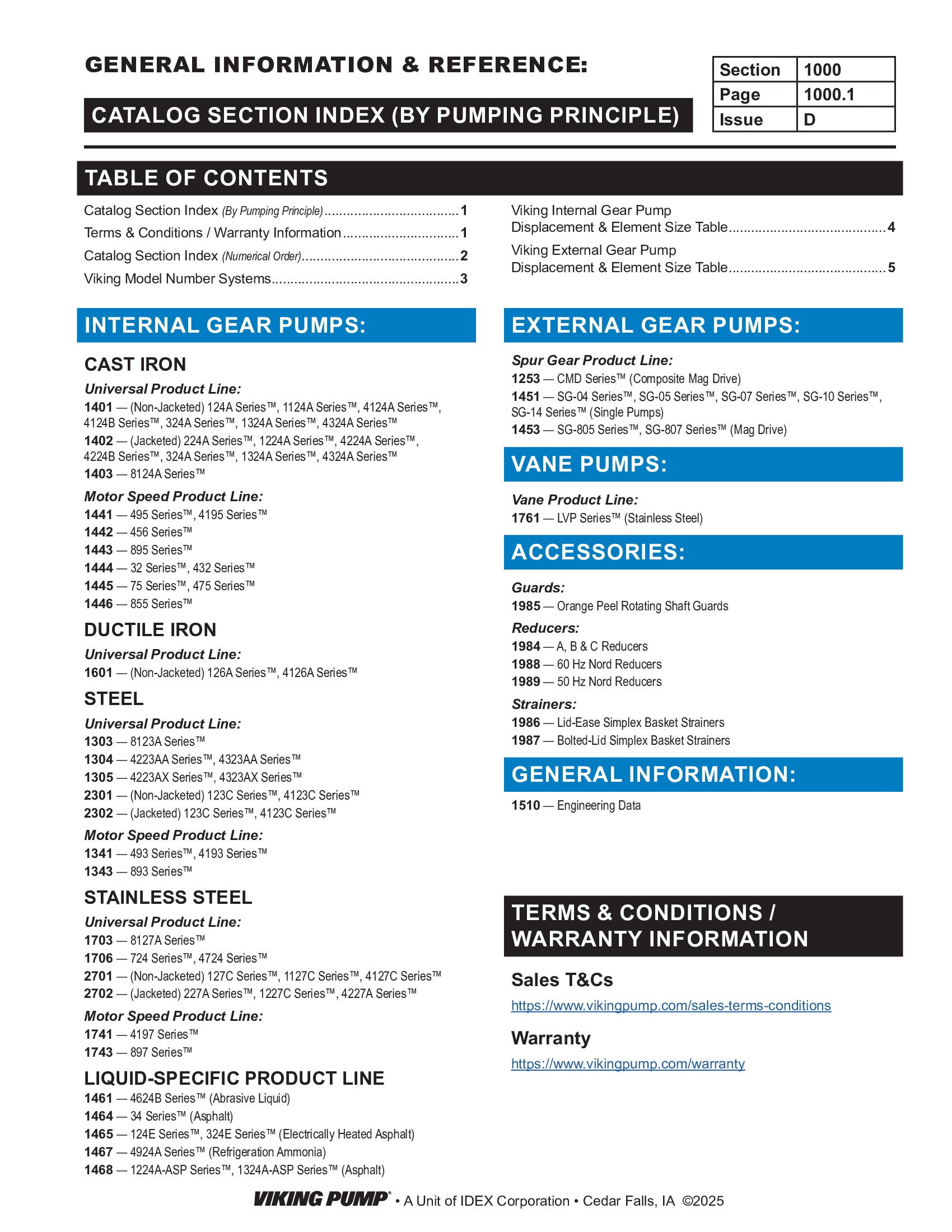
Catalog Section | 1000 | General Information
Product Flyers
Flyer | Form 2402 Jacketed
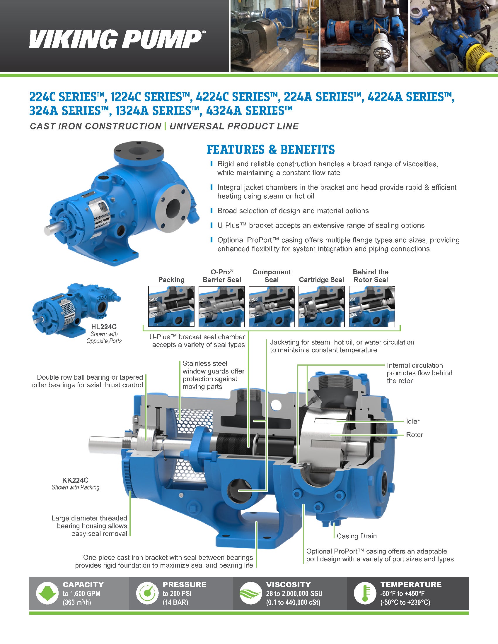
Product Flyers
Form 5000 | Product Catalog

-
DRAWINGS

H-HL with Relief Valve - 1.5" Class 125 ANSI RH/LH  PDF
PDF
H-HL with Relief Valve - 1.5" NPT RH
PDF
 STEP
STEP
K-KK with Plain Head - 2" NPT RH/LH
PDF
STEP
K-KK with Plain Head - 3" Class 125 ANSI RH
PDF
STEP
K-KK with Relief Valve - 2" NPT RH
PDF
STEP
L with Jacketed Relief Valve - 2" NPT RH
PDF
STEP
L with Jacketed Relief Valve - 3" Class 125 ANSI RH
PDF
STEP
L with Plain Head - 2" NPT RH
PDF
STEP
L with Relief Valve - 2" NPT RH/LH
PDF
STEP
LL with Jacketed Relief Valve - 3" Class 125 ANSI RH
PDF
STEP
LL with Plain Head - 3" Class 125 ANSI RH/LH
PDF
STEP
LL with Relief Valve - 3" Class 125 ANSI RH/LH
PDF
STEP
LQ with Jacketed Relief Valve - 2.5" Class 125 ANSI RH
PDF
STEP
LQ with Plain Head - 2.5" Class 125 ANSI RH/LH
PDF
STEP
LQ with Relief Valve - 2.5" Class 125 ANSI RH/LH
PDF
STEP
LS with Plain Head - 3" Class 125 ANSI RH/LH
PDF
STEP
LS with Relief Valve - 3" Class 125 ANSI RH/LH
PDF
STEP
M with Jacketed Relief Valve - 4" Class 125 ANSI RH
PDF
STEP
M with Plain Head - 4" Class 125 ANSI RH
PDF
STEP
M with Relief Valve - 4" Class 125 ANSI RH
PDF
STEP
Q with Jacketed Head - 4" Class 125 ANSI RH/LH
PDF
STEP
Q with Jacketed Relief Valve - 4" Class 125 ANSI RH
PDF
STEP
Q with Relief Valve - 4" Class 125 ANSI RH/LH
PDF
STEP
QS with Jacketed Head - 6" Class 125 ANSI Opposite
PDF
STEP
QS with Jacketed Relief Valve - 6" Class 125 ANSI Opposite
PDF
STEP
QS with Relief Valve - 6" Class 125 ANSI Opposite
PDF
STEP