 United Kingdom
 France
 Italy
Italy
 Germany
 Sweden
 Spain
Spain
 Canada
 India
India


Composé d'une lèvre élastomère flexible dans un boîtier rigide. Le joint à lèvre est fixe et l'arbre tourne à l'intérieur. Cliquez ici pour consulter le rapport sur les pompes consacré à ce sujet
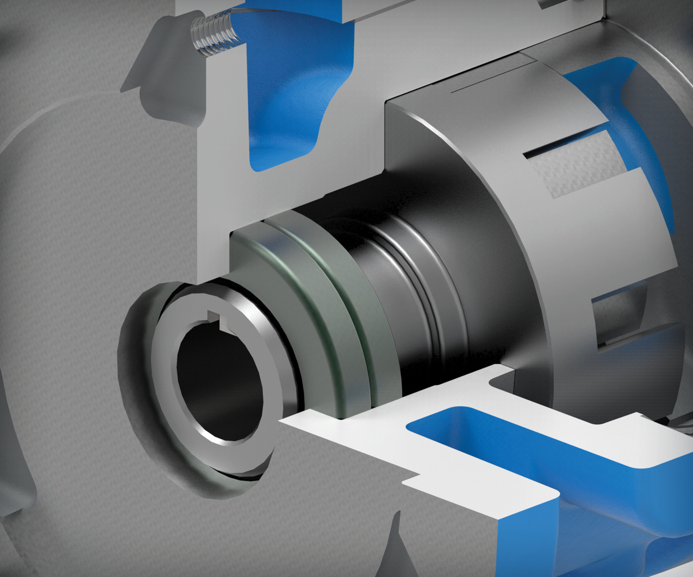
Joint à lèvre
Qu'est-ce qu'un joint à lèvre ?
Les joints à lèvre se composent d'une lèvre souple en élastomère logée dans un boîtier rigide.
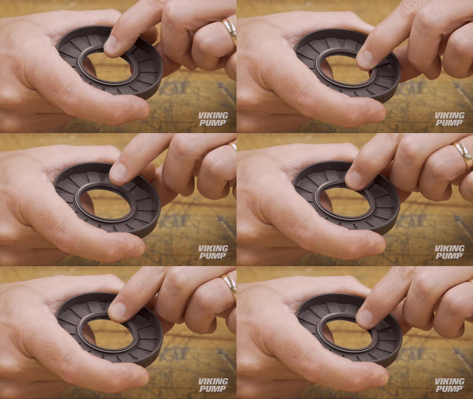
Le joint à lèvre est fixe et l'arbre tourne à l'intérieur.
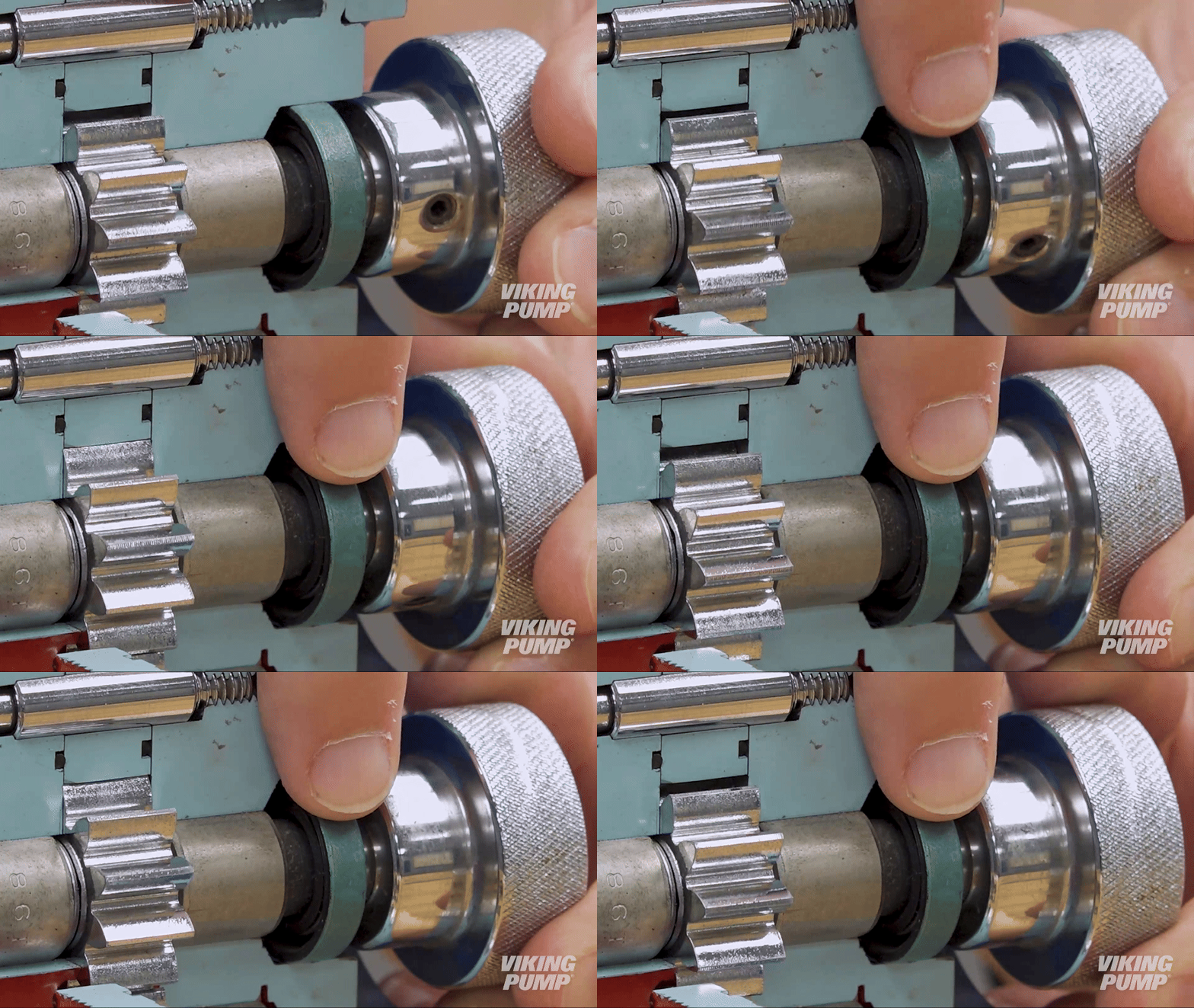
Un ressort interne contribue à maintenir la lèvre en tension et à la garder en contact avec l'arbre, tandis qu'une lèvre externe, appelée « racleur », empêche la pénétration de contaminants provenant de l'environnement extérieur.
Quels sont les avantages de l'utilisation d'un joint à lèvre dans une pompe ?
Les joints à lèvre constituent une solution d'étanchéité simple, économique et compacte. Leur profil étroit permet de les installer facilement dans des pompes de petite taille et dans des espaces restreints.
Quelles sont les limites des joints à lèvre ?
Les joints à lèvre ne sont pas adaptés aux applications abrasives et présentent des limites de pression d'entrée modestes par rapport à d'autres technologies d'étanchéité.
Comment installer un joint à lèvre
Here are some basic steps for installing a lip seal. These steps will vary depending on the type of seal and the pump technology it’s going into, but for this example these steps relate to installing a lip seal into Viking Pump’s G and GG sized 75 Series™ pumps.
Note: Before any work begins on a pump, please consult the appropriate technical service manual for safety information. A copy of the latest revision can be found on our website.
What you need for installation
To install the two lip seals into a G or GG sized 75 Series™ pump, you’ll need two pieces of equipment:
- Arbor Press
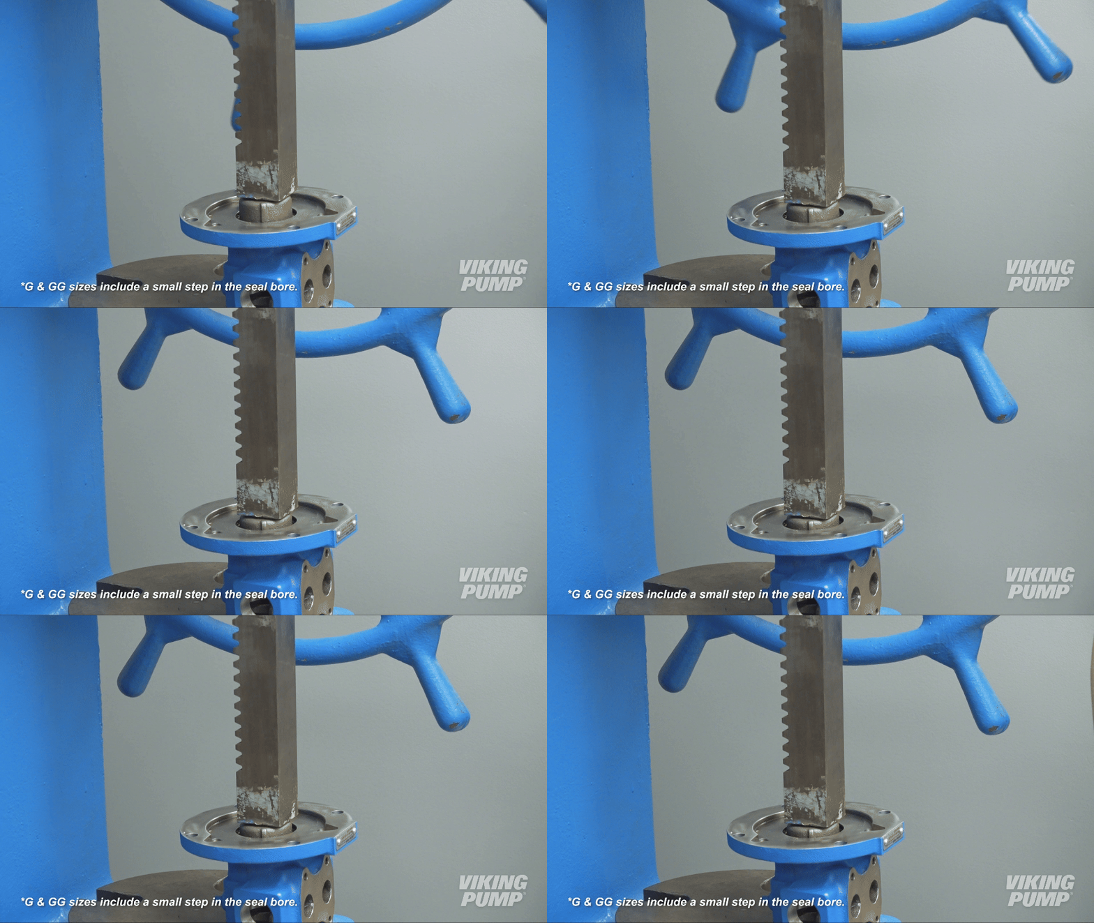
- 2 ¾” press fixture
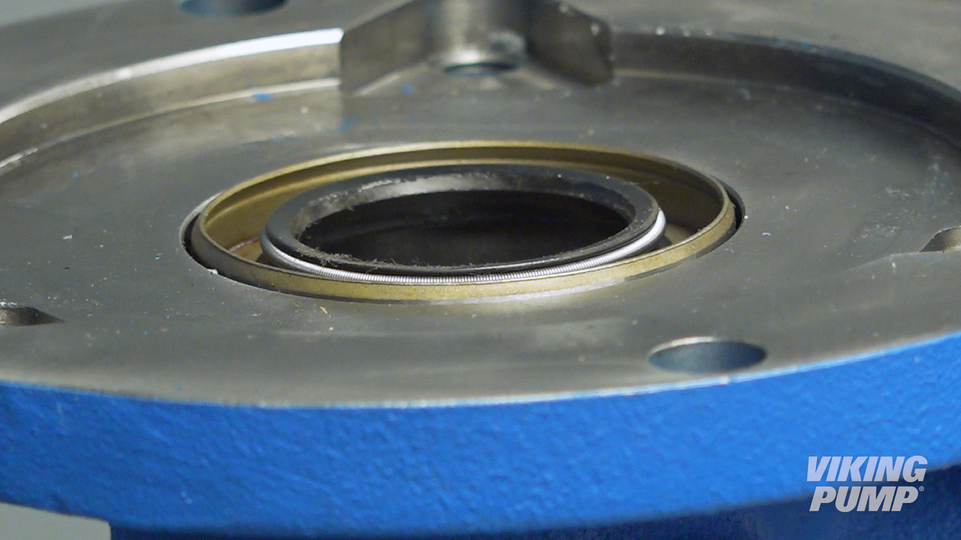
Pressing in the sealsThe 75 Series™ has two lip seals that are pressed in one at a time. The lips face outward from each other when installed. For G and GG sized pumps, the lip seals will be pressed in from the flange side of the pump. |
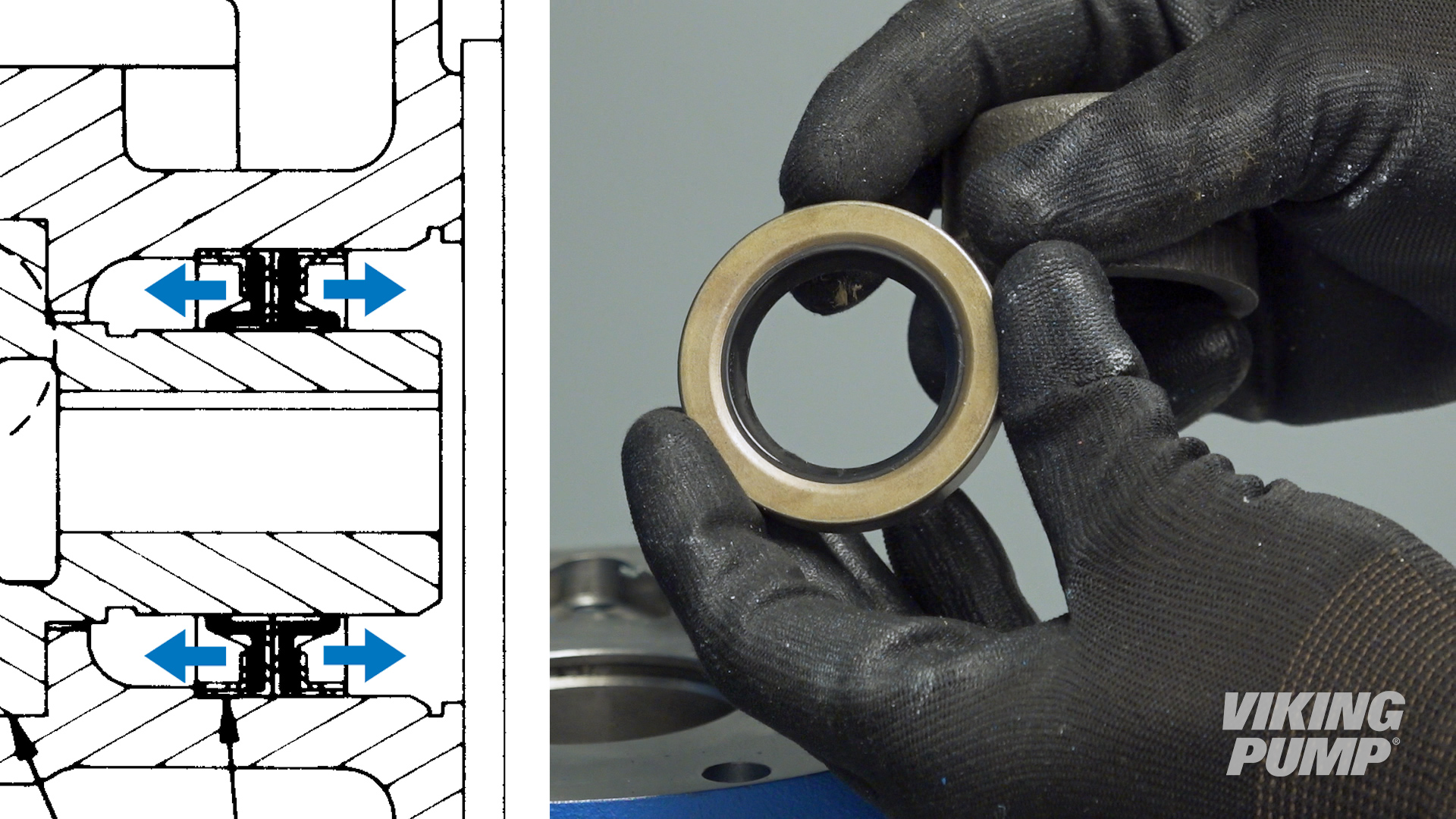 |
| Place the first lip seal into the bore with the lip down. | 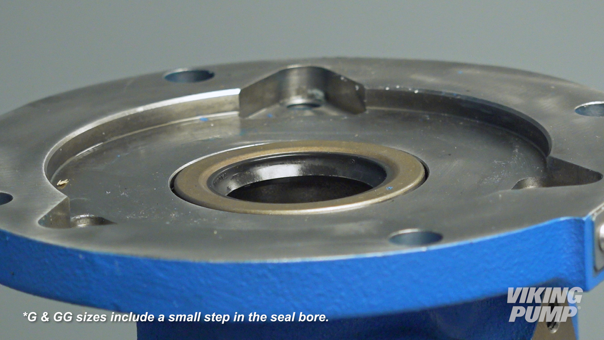 |
| Press until it stops at the bottom of the seal bore. |
|
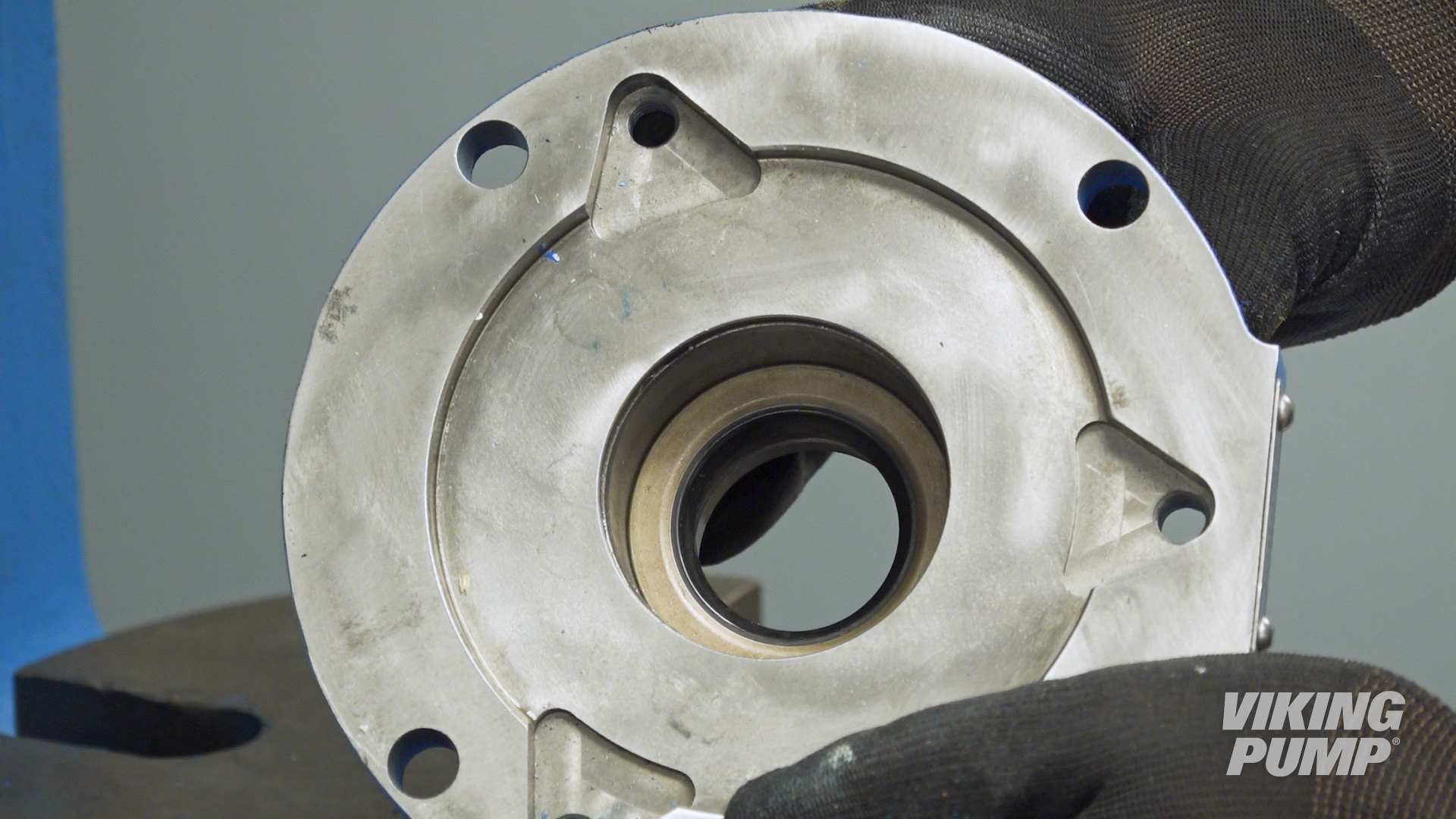
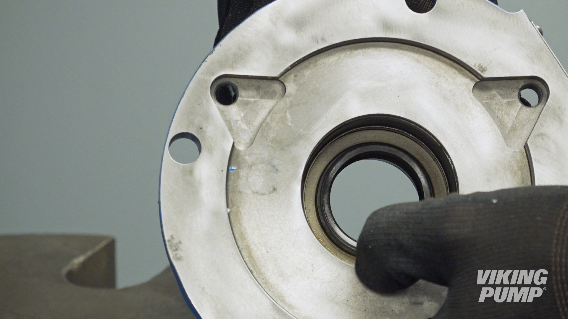
| Place the second lip seal with the lip facing up and press until it stops against the first lip seal. |
|
| Pack the area between the lips with compatible grease. | 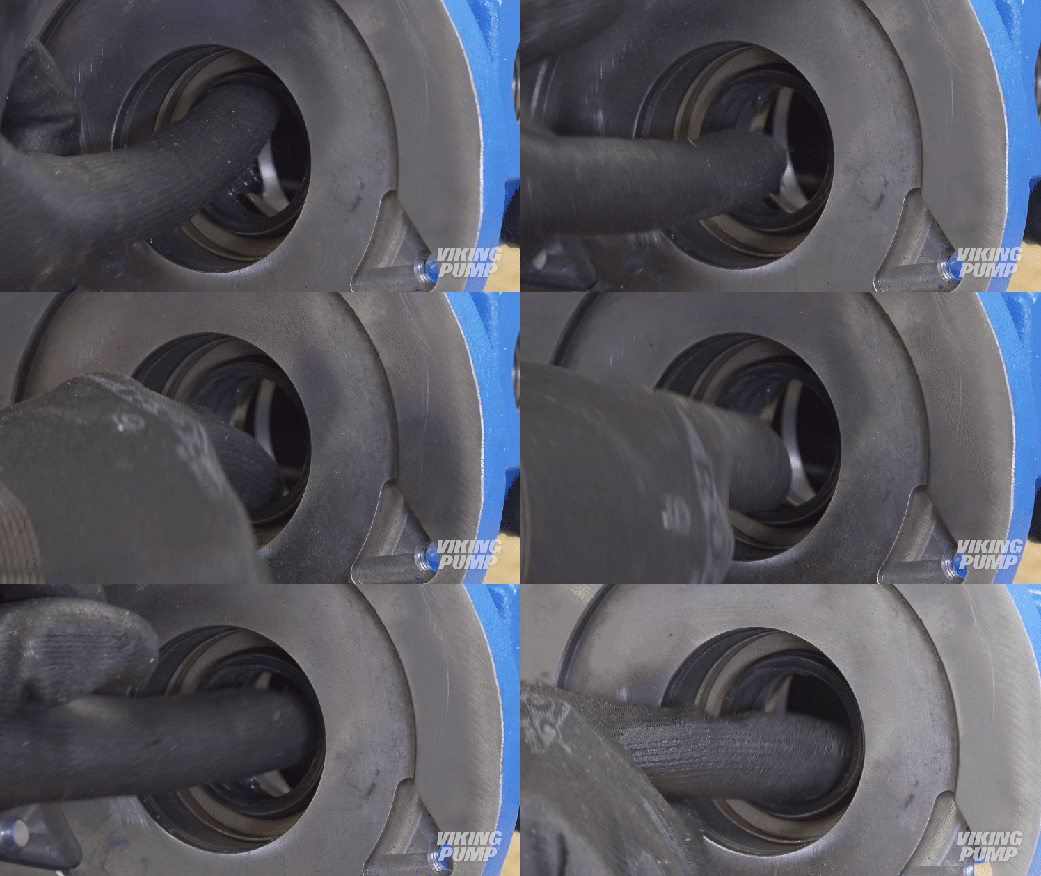 |
| You can now complete the rest of the pump assembly. | |



October 06, 2025