 United Kingdom
 France
 Italy
Italy
 Germany
 Sweden
 Spain
Spain
 Canada
 India
India


Applications
Where are Viking pumps manufactured?
Viking Pump operates a foundry, a 250,000+ sq. ft. machining, assembly and testing center, and an extensive product engineering and testing lab in its world headquarters in Cedar Falls, Iowa, USA. This level of vertical integration ensures maximum quality, ability to satisfy special needs, and to meet project schedules.
How do I find the transfer pump suitable for my application?
Viking Pump Hygienic has a strong global network of distributors ready to assist you with all of your positive displacement pump and application questions. To contact your area distributor, visit vikingpump.com/contact, enter your zip code or country, and complete the contact form. A representative will you with you soon!
Where can I view pump performance information?
Pump product details can be found on their respective product pages. Above, you'll see the list of our product offerings; select "details" to be taken to the product descriptions, which include pump performance information (capacity ranges, temperature ranges, operating pressure, etc.).
Where are Viking hygienic pumps manufactured?
Viking's hygienic positive displacement pump products are manufactured both in Cedar Falls, Iowa, USA and Eastbourne, UK.
What are the specifications for Viking industrial pumps?
Specifications can be found on the pump pages after clicking on the pump of interest. Additional specifications can be find in our related literature and catalog sections, also available on the pump pages.
Where can I purchase an industrial pump?
Viking industrial products are sold through our reliable distribution channel around the world. These distributors are trained in our product and can help install and service your pump. Find your area distributor by visiting https://www.vikingpump.com/contact.
What is the price of an industrial pump?
The price of a Viking industrial pump can span from as low as $500 to as high as $250,000. The price is largely dependent on the size and application in which it is being used. This is why our Viking experts work directly with you to evaluate your specific need so that we can recommend the pump that will give you the best return on your investment.
Components
What is a U-Plus™ bracket?
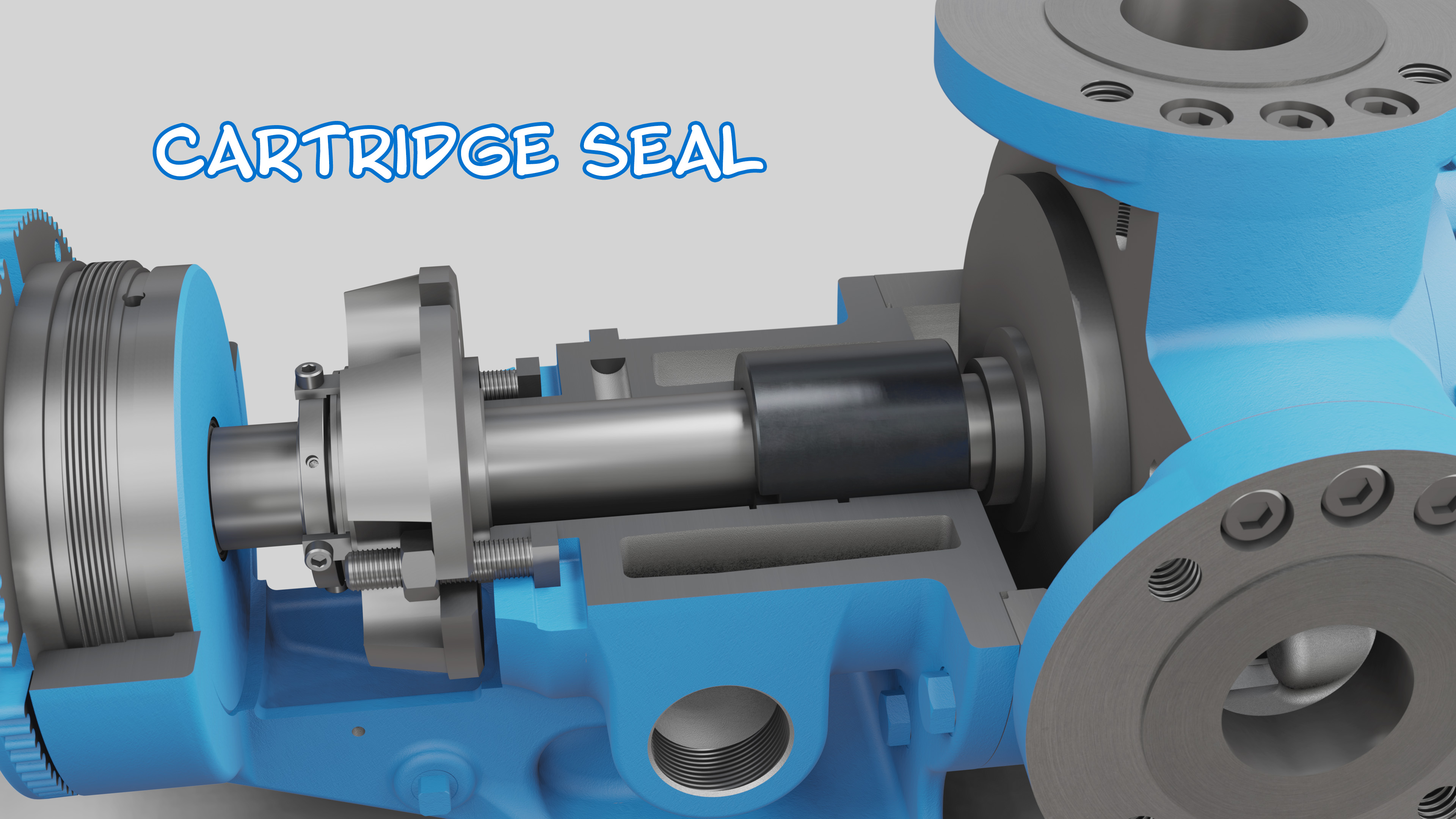
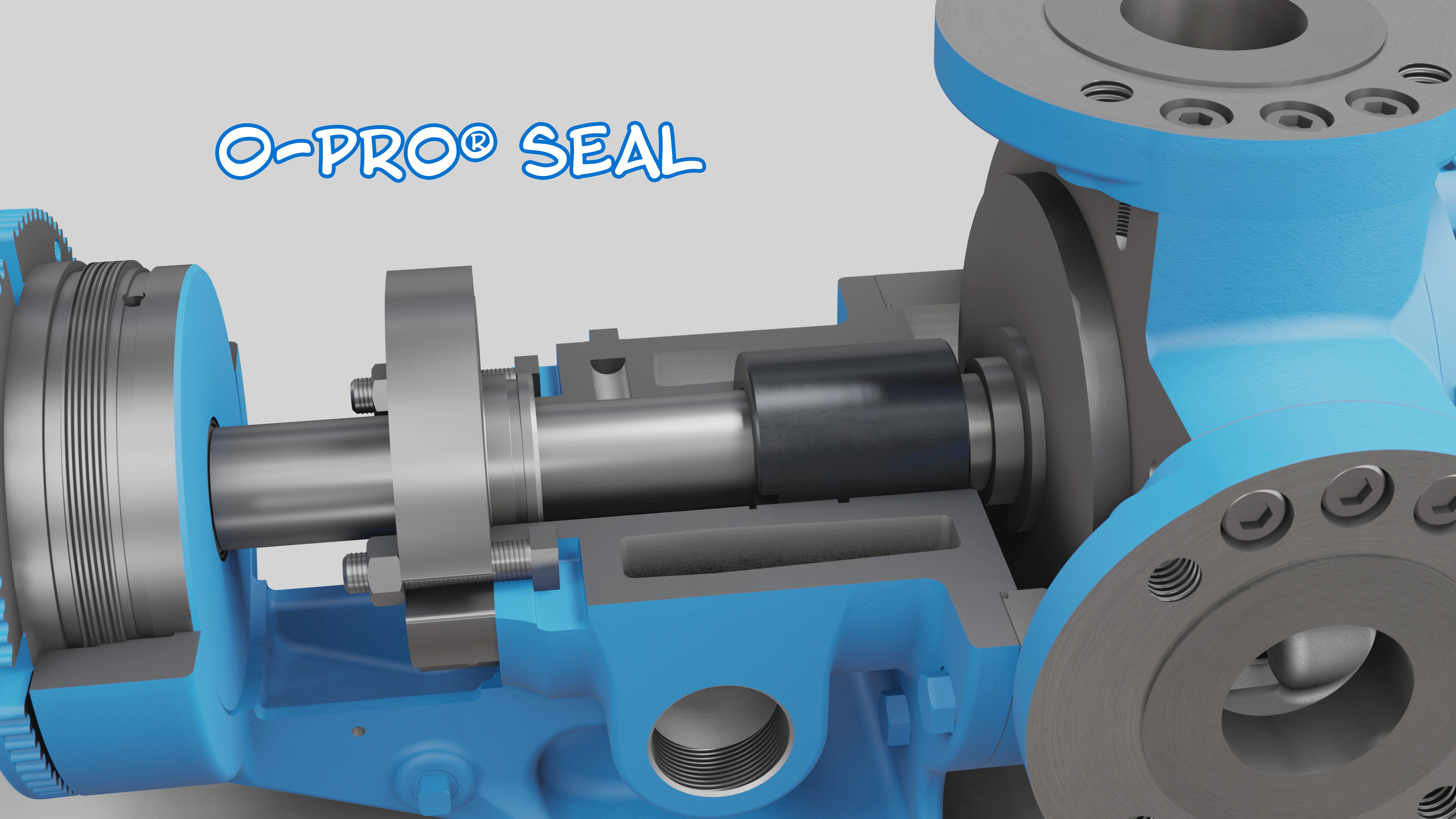
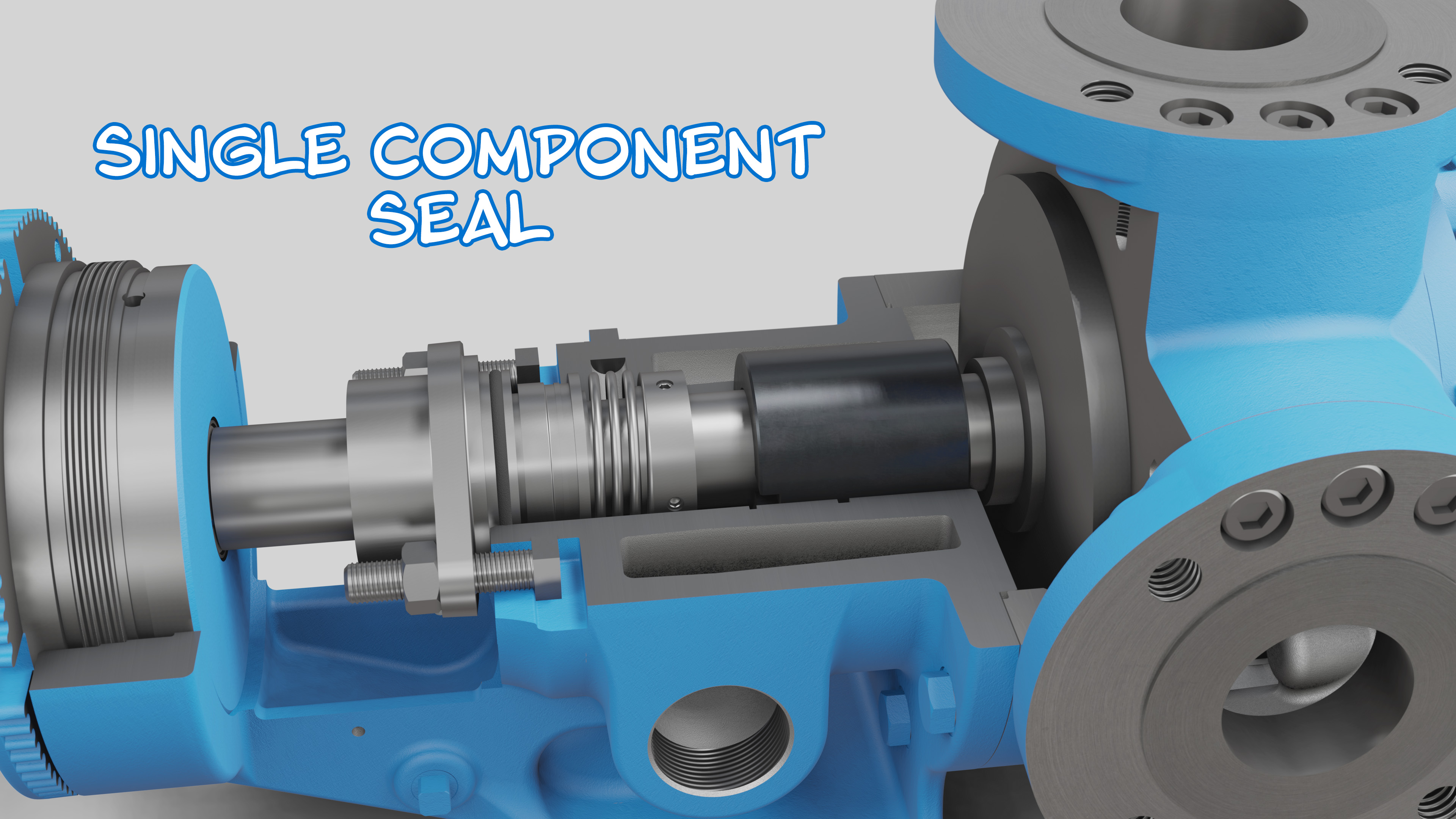
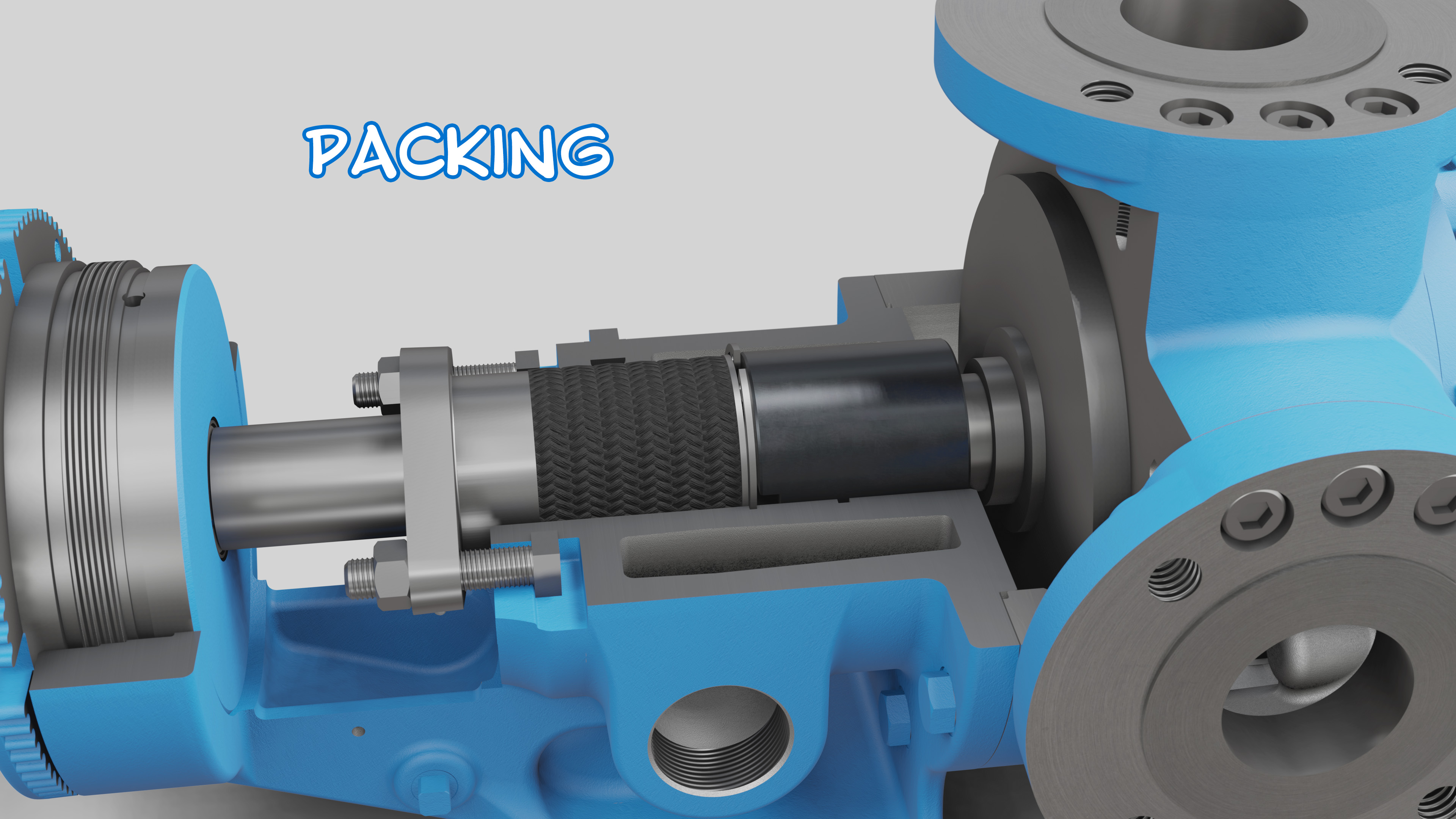
The U-Plus™ bracket is a pump bracket created by Viking Pump that is engineered to accommodate various pump sealing options including O-Pro® seals, single component mechanical seals, cartridge lip seals, cartridge single and double mechanical seals, and packing.
 |
 |
 |
 |
|
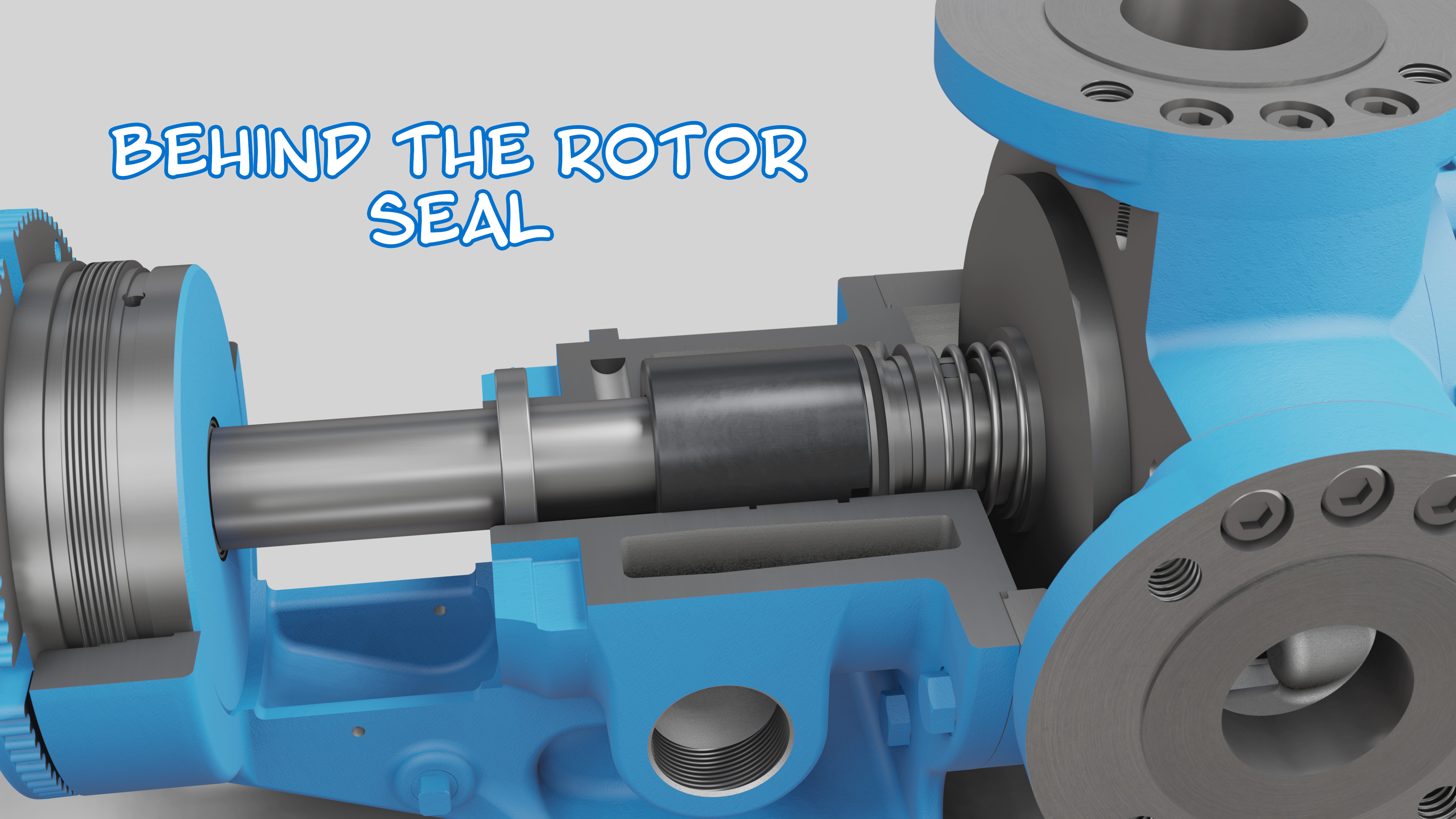
This latest version of pump bracket can also house behind the rotor seals. In legacy pumps, an entirely different bracket was needed to accomplish this.
|
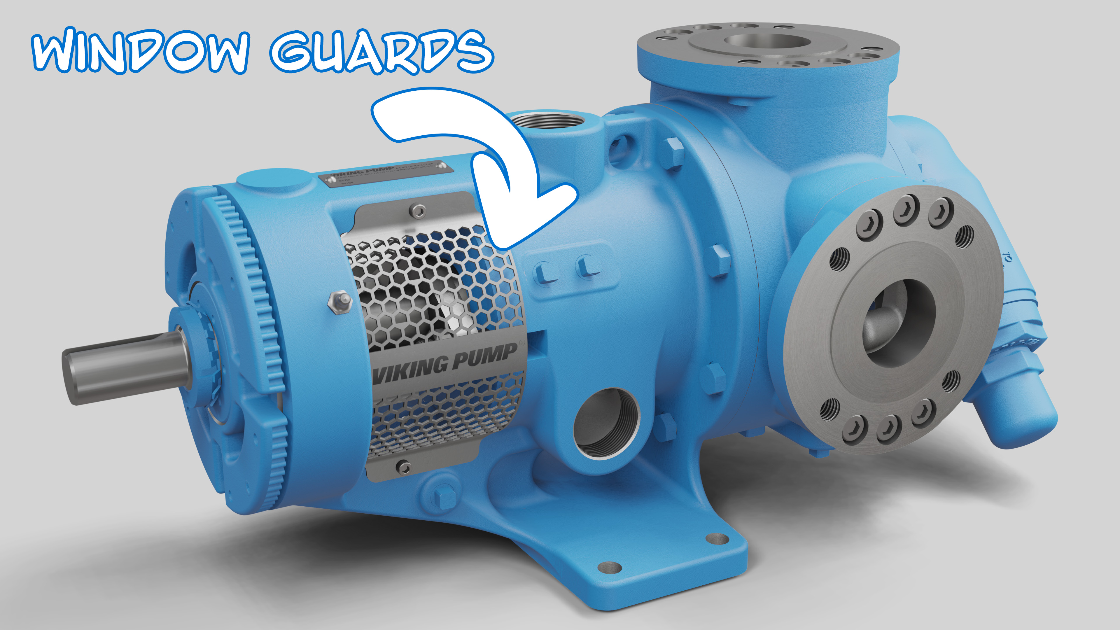
The U-Plus™ bracket also includes stainless steel window guards for protection from rotating parts.
|
Here’s a video with more about the U-Plus™ bracket: https://youtu.be/57aYvJwc9t0
What are the parts of a rotor shaft assembly?
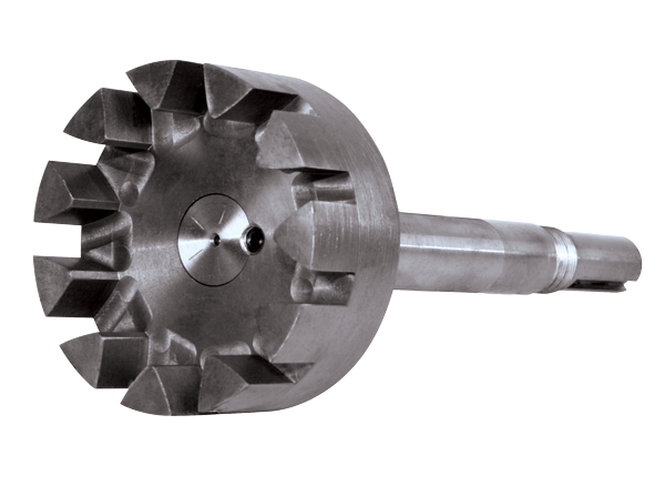
Rotor shaft assemblies consist of a shaft that is pressed into a rotor gear.
What is a pump rotor?
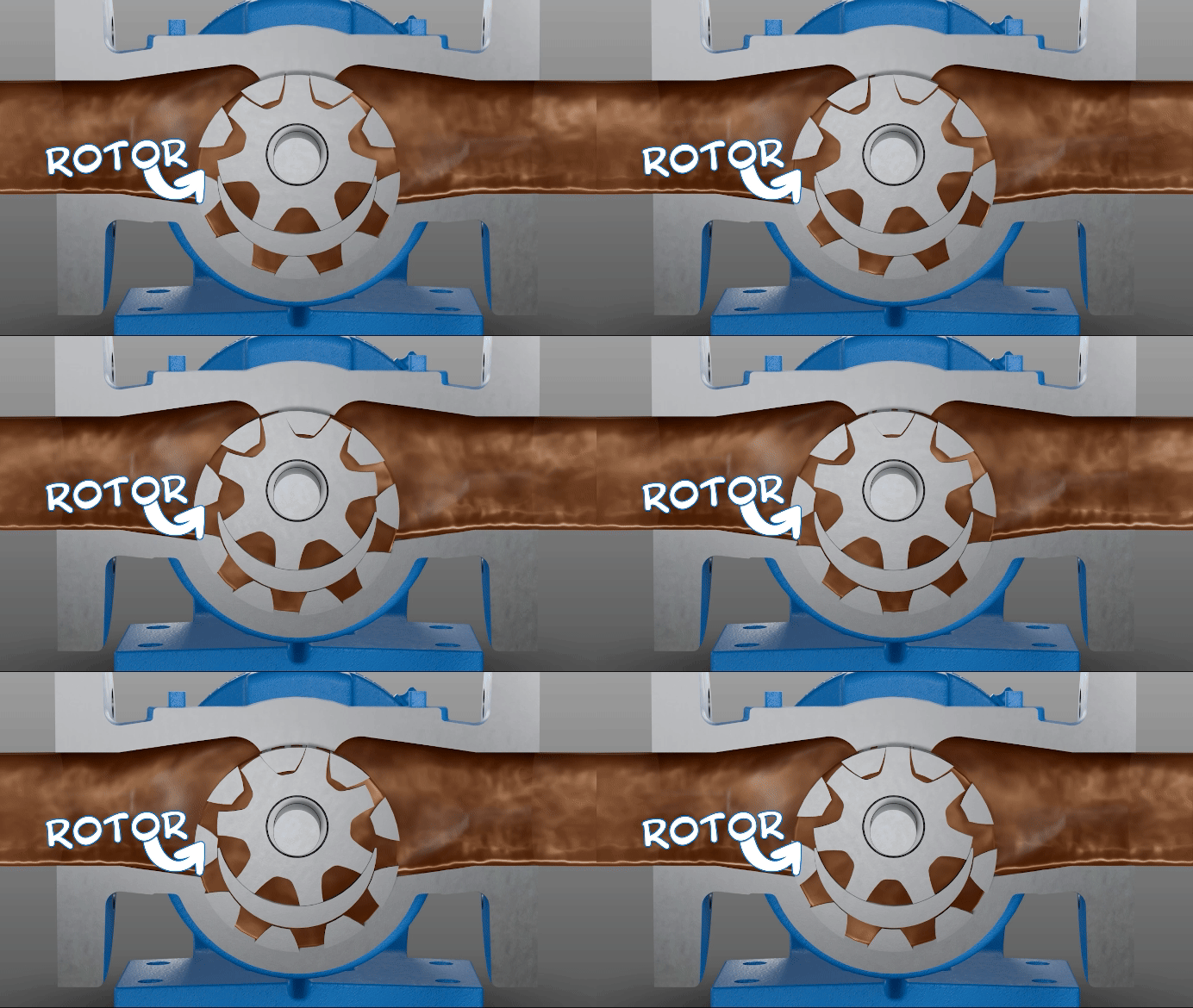
A rotor is the rotating assembly in a positive displacement pump, typically driven directly by the motor or other driver.
What is the ProPort™ casing?
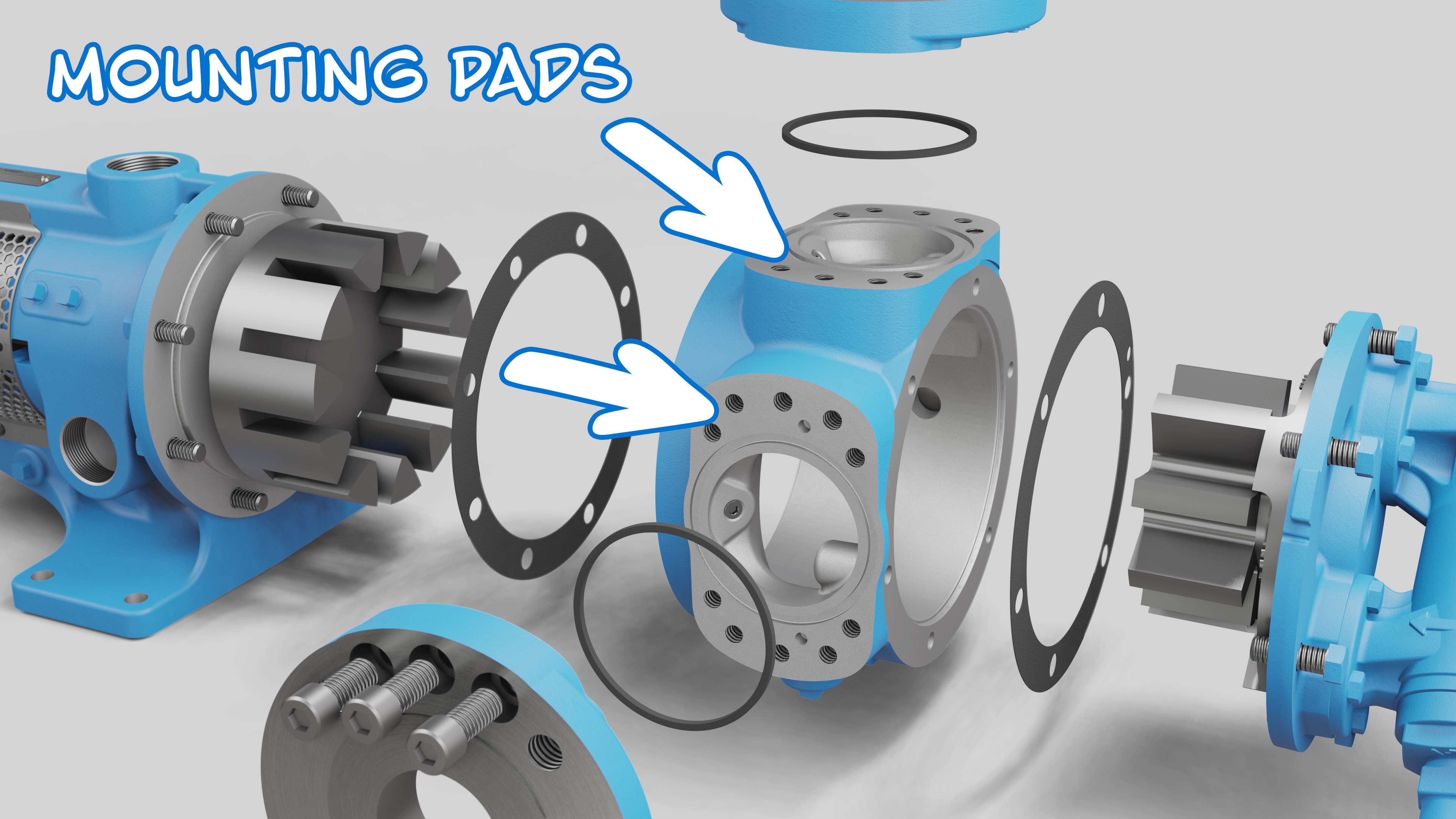
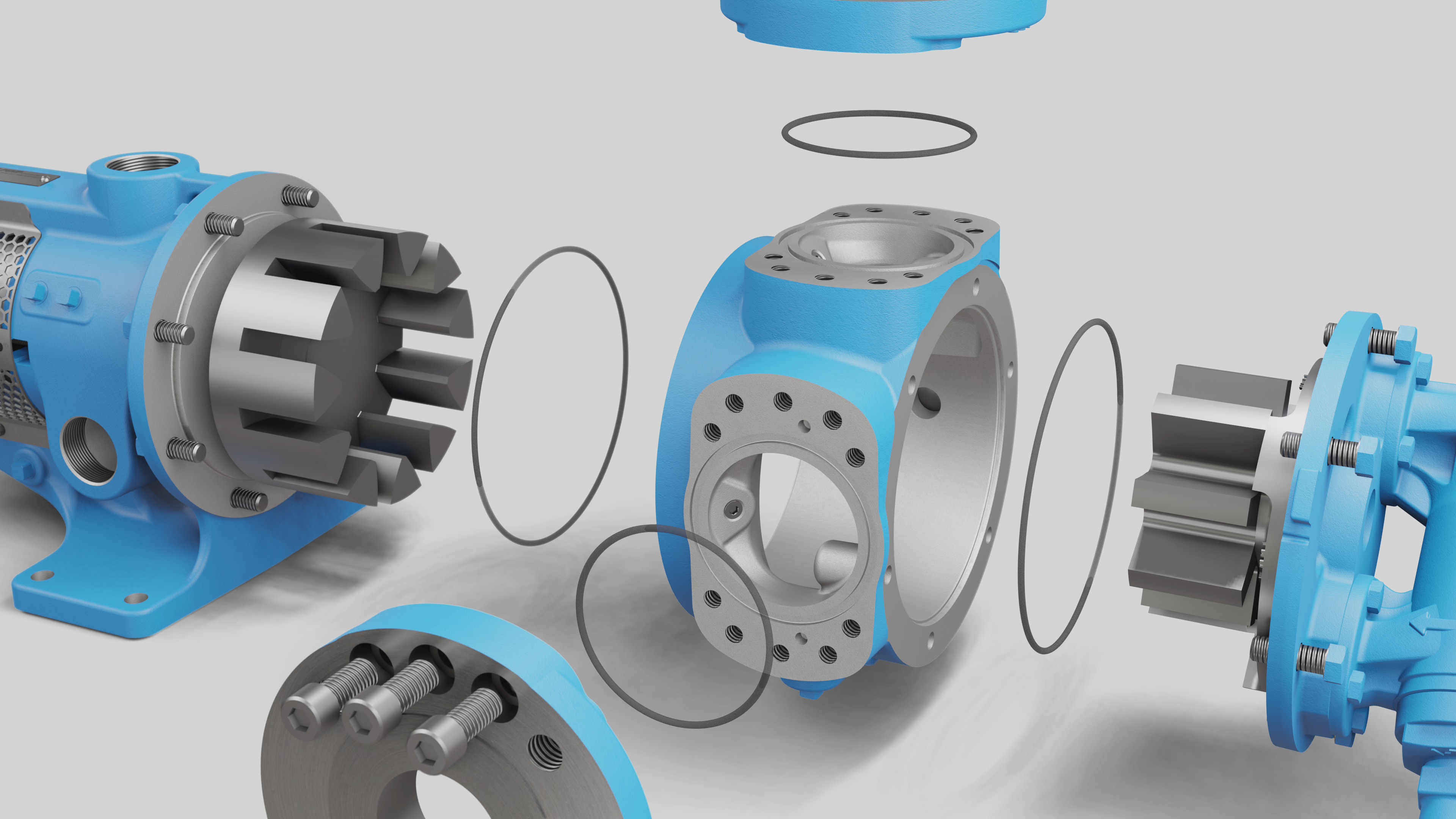
The ProPort™ casing is an adaptable Viking Pump casing design that is equipped with special mounting pads on each port location designed to accommodate a variety of port types and sizes. This feature greatly enhances the flexibility of connecting pumps to existing piping systems.
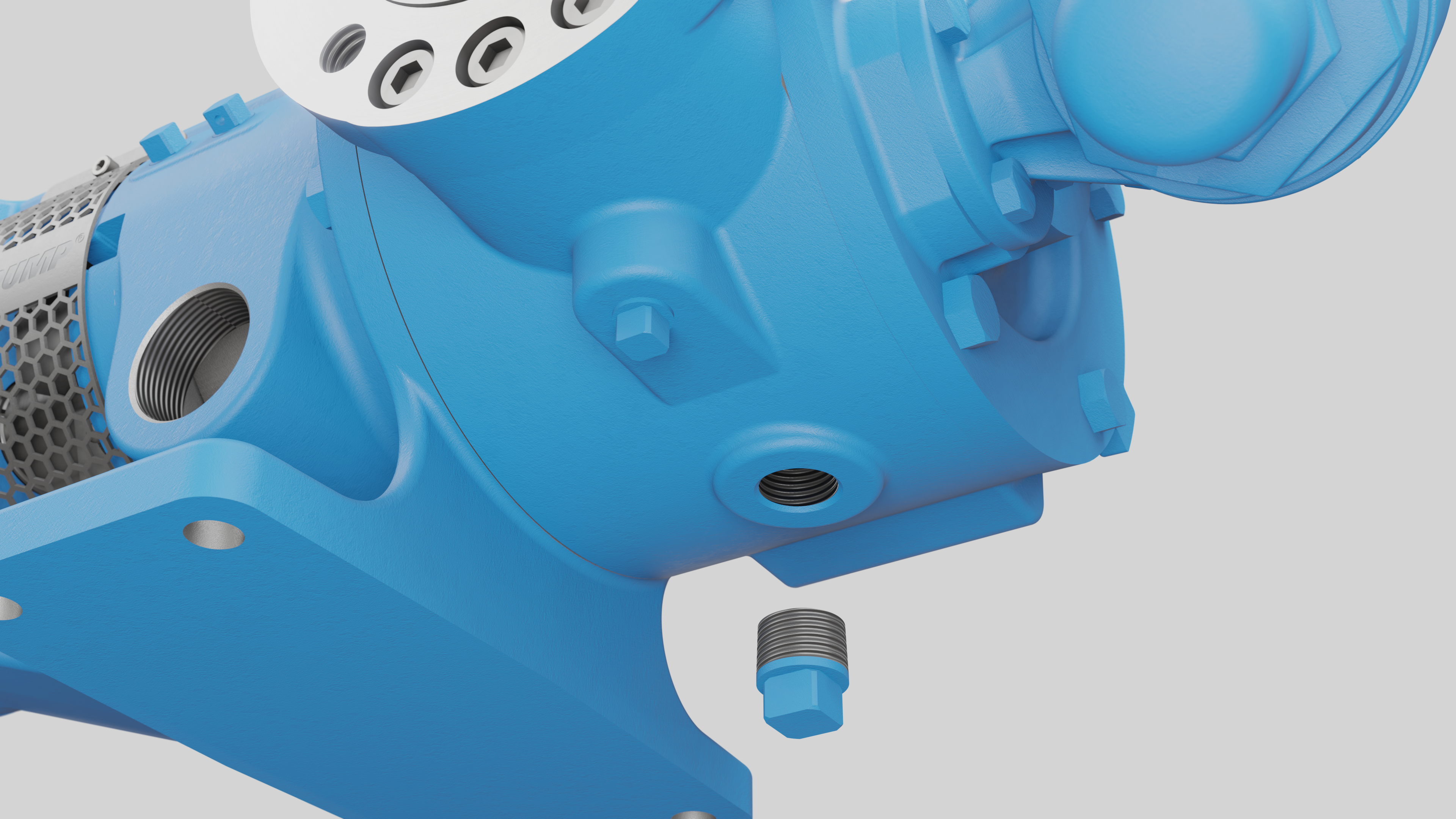
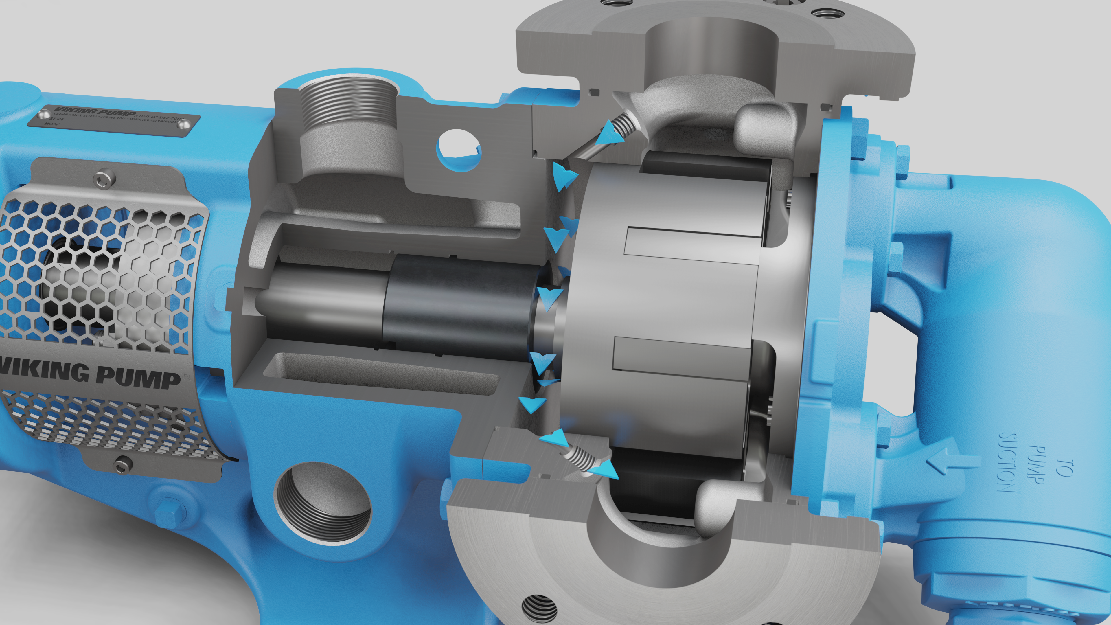
The ProPort™ Casing comes with two threaded casing drains and optional internal circulation holes, which adds to its versatility. This means fewer pump variations are necessary, simplifying inventory management and reducing costs in your facility.
 |
 |
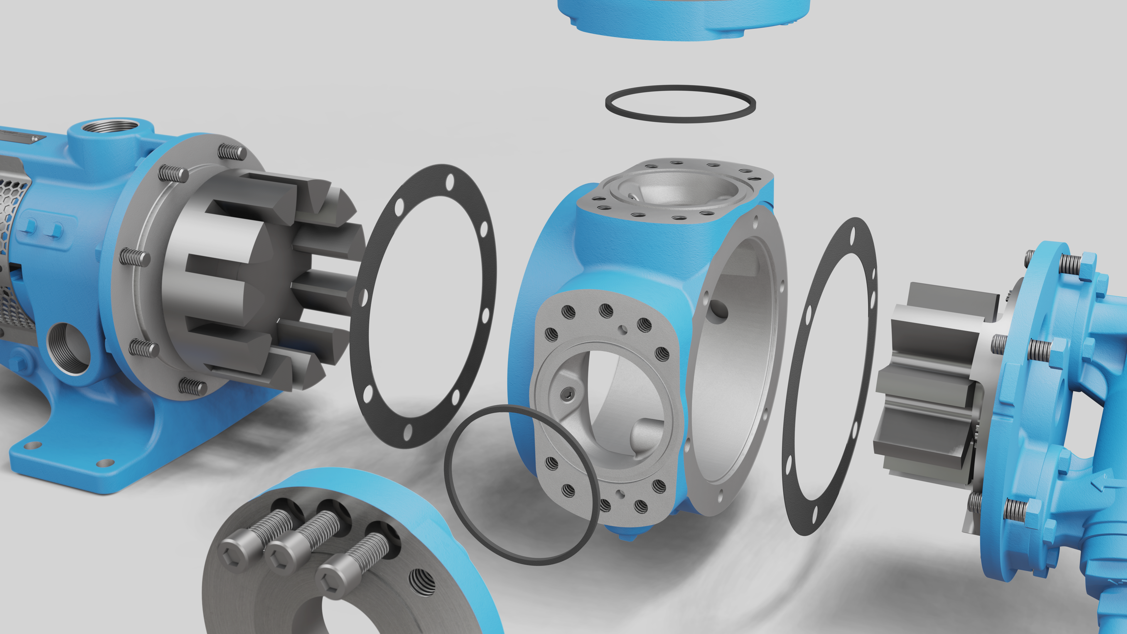
This casing design also accommodates o-rings or fiber gaskets for joint sealing between the bracket, casing, head, and ports. These features enhance the sealing ability in high-pressure or difficult-to-seal applications, ensuring that your pumping systems operate efficiently without leaks.
 |
 |
Here’s a video with more about the ProPort™ casing: https://youtu.be/57aYvJwc9t0
What are the parts of an idler gear?
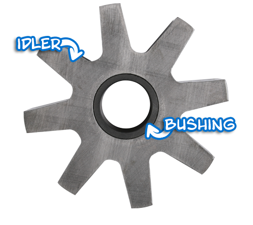
There are two components in an idler gear: the idler itself and the idler bushing. Each of these components can be made of various materials that can change depending on pump construction and application.
What is an idler gear?
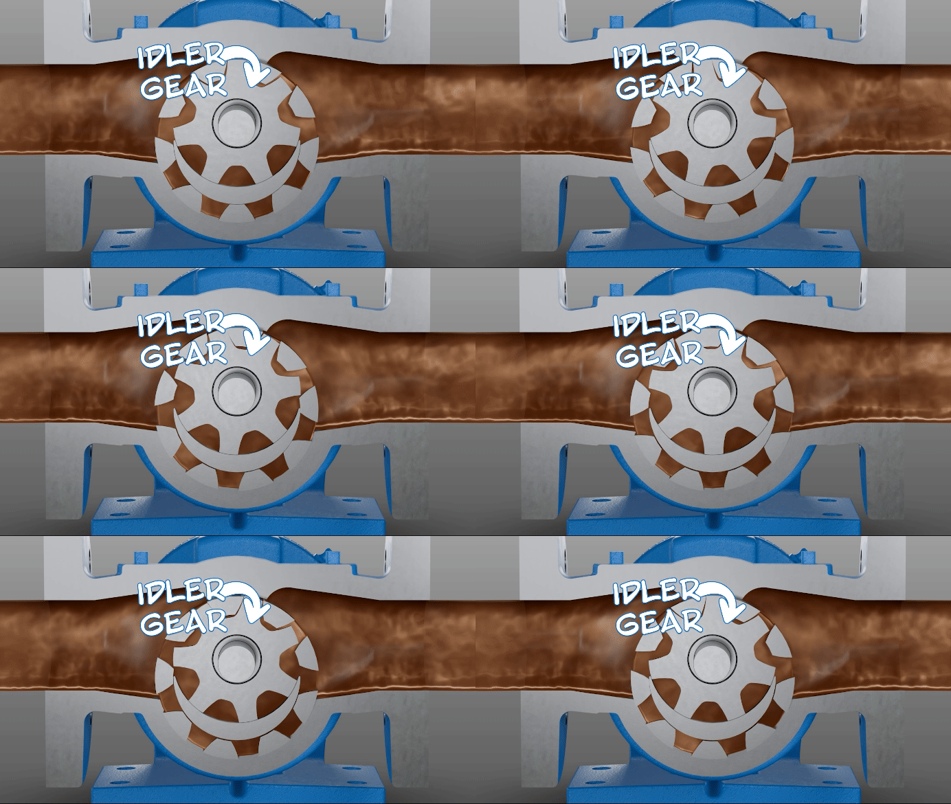
An idler gear is a key component in internal gear pumps. This is a free-rotating gear that is driven by the rotor gear.
What clearances are available on your products?
We offer adjustable clearances as a standard that enables handling viscosities from 28 to 2,000,000 SSU (1 to 440,00 cSt). Our internal gear products also have low shear to protect your liquids and a smooth, non-pulsating flow for accurate measurement or metering.
Flow & Conversions
What does “barrels per hour” mean?
Barrels per hour is a common flow rate measurement in the oil and gas industry. One “barrel” is equivalent to 42 US gallons (159 liters) – and became the standard US measurement in 1872. This unit of flow rate provides a practical way of calculating the larger volumes of oil over a longer timeframe.
The 55-gallon steel drums commonly associated with oil storage are not tied to the flow rate calculation of “barrels per day.”
Converting liters per minute (LPM) to cubic meters per hour (m3/h)
m3/h = LPM x 0.06
Converting gallons per minute (GPM) to liters per minute (LPM)
LPM = GPM / .2642
Converting liters per minute (LPM) to gallons per minute (GPM)
GPM = LPM x .2642
Liters per minute and flow measurement
Liters per minute (LPM) is a unit of flow measurement.
Liters per hour and flow measurement
Liters per hour (LPH) is a unit of flow measurement.
Converting cubic meters per hour (m3/h) to liters per hour (LPH)
LPH = m3/h x 1000
Converting liters per hour (LPH) to cubic meters per hour (m3/h)
m3/h = LPH / .001
Converting gallons per minute (GPM) to liters per hour (LPH)
LPH = GPM / .0044
Converting liters per hour (LPH) to gallons per minute (GPM)
GPM = LPH x .0044
Convert from UK GPM to US GPM
US GPM = UK GPM x 1.2
Convert from US GPM to UK GPM
UK GPM = US GPM / 1.2
What’s the difference between US and UK gallons per minute?
Depending on where you’re at, it is important to understand that the term “gallon” may be slightly different. The US standard gallon is 128 fluid ounces, while the UK Imperial gallon is 160 fluid ounces.
What is gallons per minute?
Gallons per minute is a unit of flow measurement. If a pump transfers 4,000 gallons of liquid in 1 hour, the pump is operating at just over 66 GPM.
Convert from UK GPH to US GPH
US GPH = UK GPH x 1.2
Convert from US GPH to UK GPH
UK GPH = US GPH / 1.2
Convert from GPM to GPH
GPH = GPM x 60
Convert from GPH to GPM
GPM = GPH / 60
What’s the difference between US and UK gallons per hour?
Depending on where you’re at, it is important to understand that the term “gallon” may be slightly different. The US standard gallon is 128 fluid ounces, while the UK Imperial gallon is 160 fluid ounces.
What is gallons per hour?
Gallons per minute is a unit of flow measurement. If a pump transfers 4,000 gallons of liquid in 20 minutes, the pump is operating at 12,000 GPH.
Converting cubic meters per hour (m3/h) to liters per minute (LPM)
LPM = m3/h x 16.6667
Converting cubic meters per hour (m3/h) to gallons per minute (GPM)
GPM = m3/h x 4.4029
Cubic meters per hour and flow measurement
Cubic meters per hour (m3/h) is a unit of flow measurement.
Converting gallons per minute to barrels per hour (bbl/hr)
bbl/hr = (gpm x 60) / 42
or
bbl/hr = gpm x 1.429
Converting gallons per minute to barrels per day (bbl/day)
bbl/day = 24(gpm x 60) / 42
What does “barrels per day” mean?
Barrels per day is a common flow rate measurement in the oil and gas industry. One “barrel” is equivalent to 42 US gallons (159 liters) – and became the standard US measurement in 1872. This unit of flow rate provides a practical way of calculating the larger volumes of oil over a longer timeframe.
The 55-gallon steel drums commonly associated with oil storage are not tied to the flow rate calculation of “barrels per day.”
What is the maximum flow rate of Viking's hygienic pumps?
| Pump Models | MAX Flow Rate (GPM) | MAX Flow Rate (m³/h) |
|---|---|---|
| Revolution® Series | 399 | 91 |
| Classic+ Series® / Multipump® Series |
450 | 102 |
| TRA®10 & TRA®20 Series | 832 | 182 |
| RTP® Series | 338 | 76.8 |
Click the pump model name to be routed to that pump's product description page.
General
What are Newton meters?
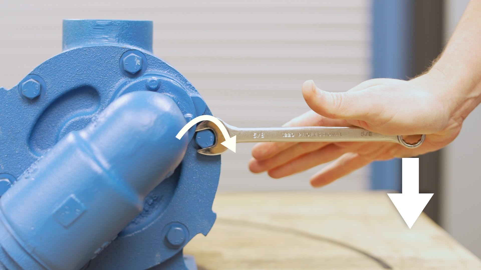
Newton meters (Nm) are a unit of torque measurement – representing one newton of force acting at a perpendicular distance of one meter from a pivot point.
How to convert pound feet to newton meters?
Another common unit of torque measurement is newton meters. Here are the conversion formulas:
N-M = lb.ft. x 1.359
Lb.ft = (N-M) / 0.738
What are foot pounds?
Foot pounts (ft.lbs.), or pound feet (lb.ft.), is a unit of torque measurement – representing a point of force acting at a perpendicular distance of one foot from a pivot point.
Why is it called “brake” horsepower?
When motors are tested, they are run at a specified RPM and brakes are applied to the shaft to measure the torque output. Power is the product of torque an RPM. Since brakes are applied in the test, that’s where the term “brake” horsepower comes from.
Power = Torque x RPM
What is brake horsepower?
Brake horsepower is a measurement of a motor’s power at the shaft before losing power due to resistance of auxiliary components (reducers, couplings, pump). Essentially, the brake horsepower of a motor (bhp) will always be higher than the listed horsepower (hp).
What does API mean?
API stands for the American Petroleum Institute – which maintains industry standard practices for the oil and gas industry. These standards promote safety, environmental protection, and sustainability.
Pressure
How to relief valves on pumps work?
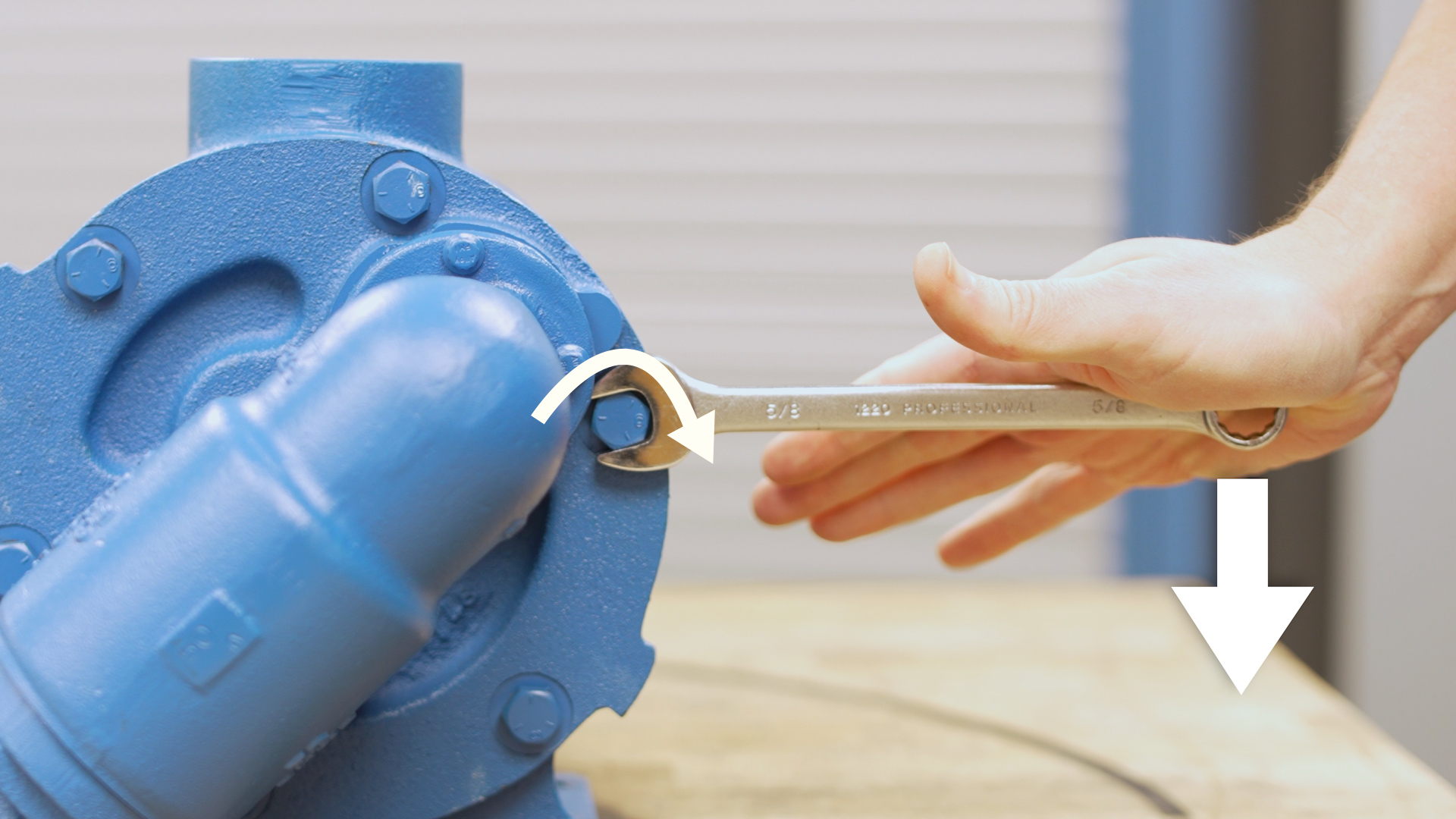
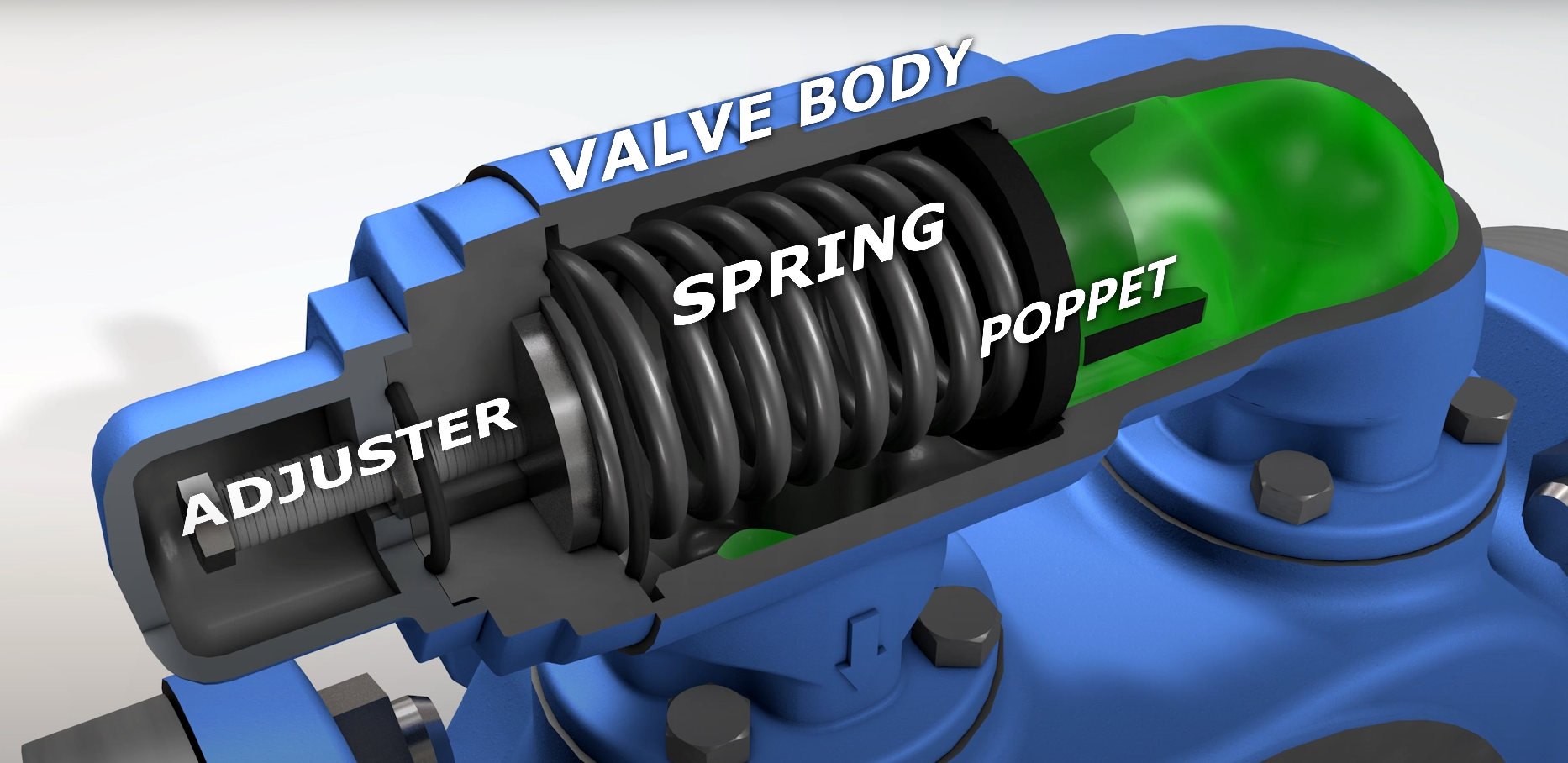
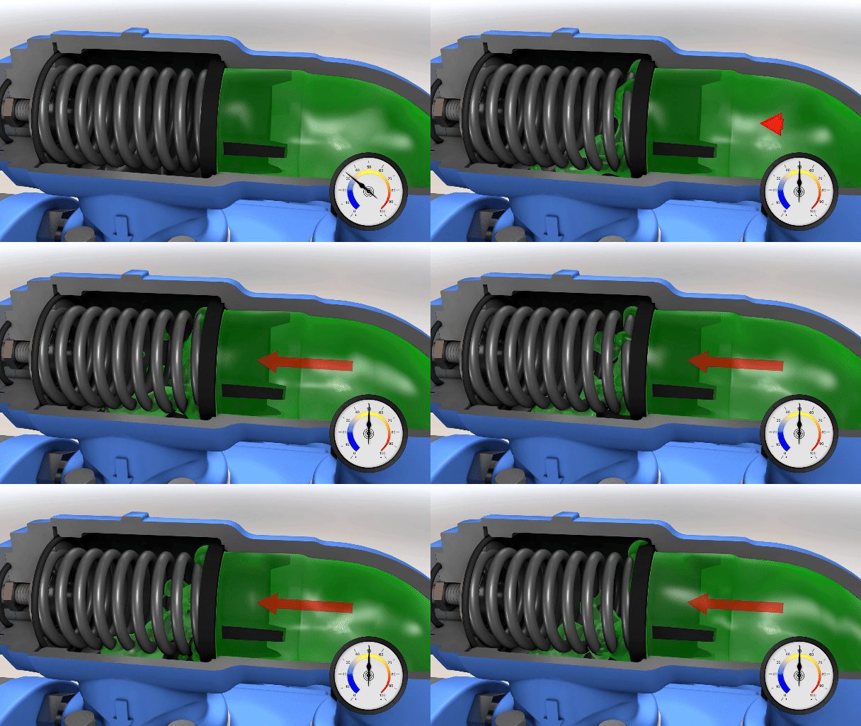
In a process, if the liquid is prevented from being delivered by a blocked or closed discharge line, pressure can build. This buildup of pressure can stall the motor, damage drive equipment, damage the pump, or even burst hoses or piping. To prevent this, pressure relief valves a common choice. The valve consists of several key components: The valve body which houses the internals and connects the valve to the pump, a moving poppet, one or more springs, and an adjusting screw to compress the springs and adjust the pressure setting.
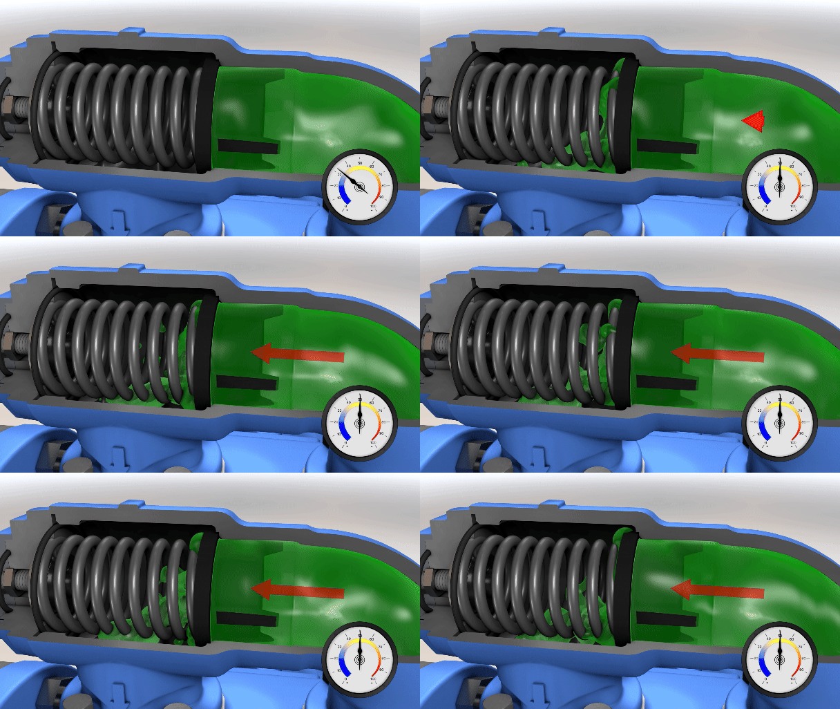
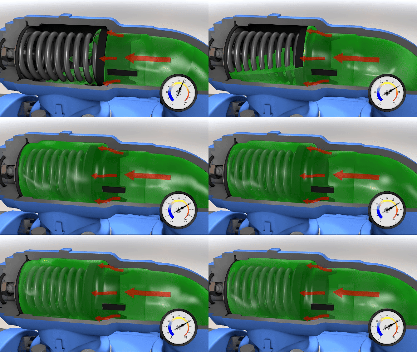
As pressure at the valve inlet increases, it eventually reaches a point where the spring compresses slightly, moving the poppet and bypassing a small amount of pumped liquid. This is known as the “cracking pressure” of the valve. In an internal relief valve, this flow is diverted back to the suction side of the pump. If pressure continues to build, the valve will open more to divert more flow back to the suction side. If the discharge line is blocked or closed entirely then 100% of the pump’s capacity is cycled through the valve. This is called the “full bypass pressure." When the pressure returns to normal, the spring moves the poppet to close the valve and the pump returns to full capacity.
What is a pump relief valve?
A relief valve (or pressure relief valve) is a mechanical device designed to bypass flow in the result of an overpressure condition at the outlet port of the pump.
Watch a video about relief valves here.
What does PSI mean?
PSI, or pounds per square inch, is a unit of pressure that measures the amount of force (in pounds) that is applied to one square inch of surface area.
Understanding net positive suction head (NPSH)
NPSHA is a function of your system and must be calculated, whereas NPSHR is a function of the pump and must be provided by the pump manufacturer. NPSHA MUST be greater than NPSHR for the pump system to operate without cavitating. You must have more suction side pressure available than the pump requires or cavitation will occur.
What is net positive suction head (NPSH)?
Net positive suction head is the absolute head required at the inlet of the pump to prevent cavitation. Similar to net positive inlet pressure (NPIP).
Net positive suction head can be noted with the suffix “A” (NPSHA) for available NPSH from the system or "R" (NPSHR) for NPSH required by the pump. Similar to Net Positive inlet pressure (NPIP).
What is cavitation?
Pump cavitation occurs when the pressure at the pump inlet drops below the vapor pressure of the liquid. Vapor bubbles form at the inlet of the pump and are moved to the outlet where they collapse, often taking small pieces of the pump with them.
Cavitation is often characterized by:
- Loud noise often described as a grinding or “marbles” in the pump
- Loss of capacity (bubbles are now taking up space where liquid should be)
- Pitting damage to parts as material is removed by the collapsing bubbles
To learn more, watch this video about cavitation.
What is net positive inlet pressure (NPIP)?
Net positive inlet pressure is the absolute pressure required at the inlet of the pump to prevent cavitation. Similar to net positive suction head (NPSH).
Net positive inlet pressure can be noted with the suffix “A” (NPIPa) for available NPIP from the system or "R" (NPIPr) for NPIP required by the pump. Similar to Net Positive Suction Head (NPSH).
Why is knowing maximum differential pressure important?
Knowing the maximum differential pressure is important so that the pump is operated safely. Exceeding this value can lead to damaging the pump or system.
How do I find my pump's maximum differential pressure?
The maximum differential pressure is provided by Viking Pump’s Pump Selector program or Catalog Performance Curves – but may be increased or decreased depending on the application specifics, pump size, and construction. This may be less than or equal to the full bypass pressure of the relief valve.
What is maximum differential pressure?
Maximum differential pressure is the maximum allowable difference between the discharge pressure and the inlet pressure for a given set of operating conditions.
Why is knowing maximum allowable working pressure important?
Knowing the maximum allowable working pressure is important so that the pump is operated safely. Exceeding the MAWP can lead to damaging the pump or system.
How to calculate maximum allowable working pressure?
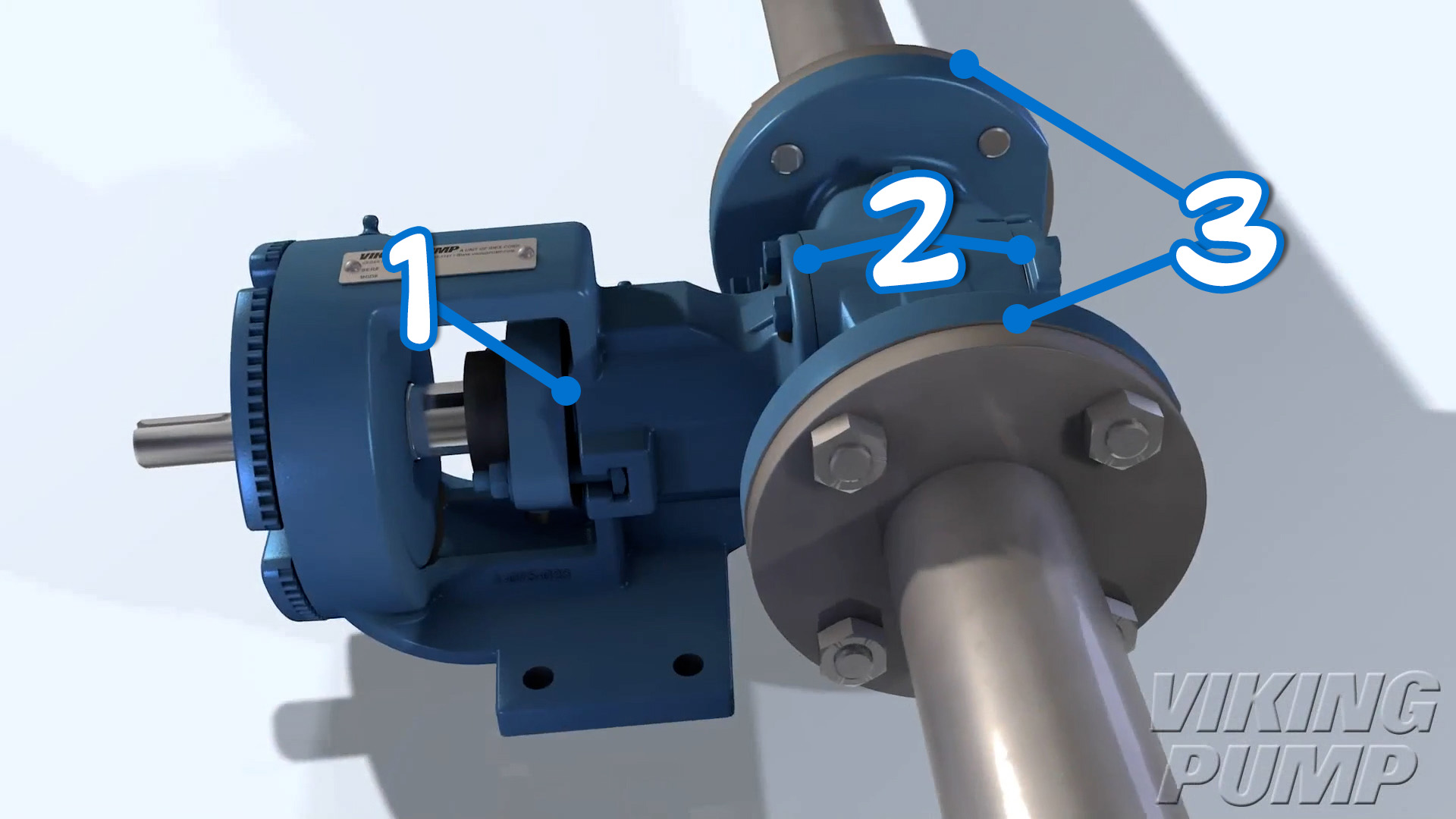
Maximum allowable working pressure can be established as the lowest pressure limit of the following 3 components:
1) Shaft Seal
2) Joint Seals
3) Port Connections
What is maximum allowable working pressure (MAWP)?
Maximum allowable working pressure (MAWP), is the maximum continuous pressure for which the pump is designed to handle.
Why is knowing maximum allowable inlet pressure important?
Knowing the maximum allowable inlet pressure is important so that the pump is operated safely. Exceeding the MASP can lead to damaging the pump or system.
How to calculate maximum allowable inlet pressure?
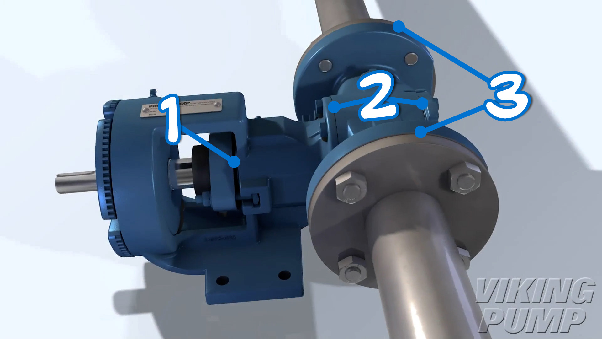
Maximum allowable inlet pressure can be established as the lowest pressure limit of the following 3 components:
1) Shaft Seal
2) Joint Seals
3) Port Connections
What is maximum allowable inlet pressure (MASP)?
Maximum allowable inlet pressure, also known as maximum allowable suction pressure (MASP), is the maximum allowable difference between the absolute pressure of the fluid at the inlet port and the absolute ambient pressure.
Why is knowing maximum allowable casing pressure important?
Knowing the maximum allowable casing pressure is important so that the pump is operated safely. Exceeding the MACP can lead to damaging the pump or system.
How to calculate maximum allowable casing pressure
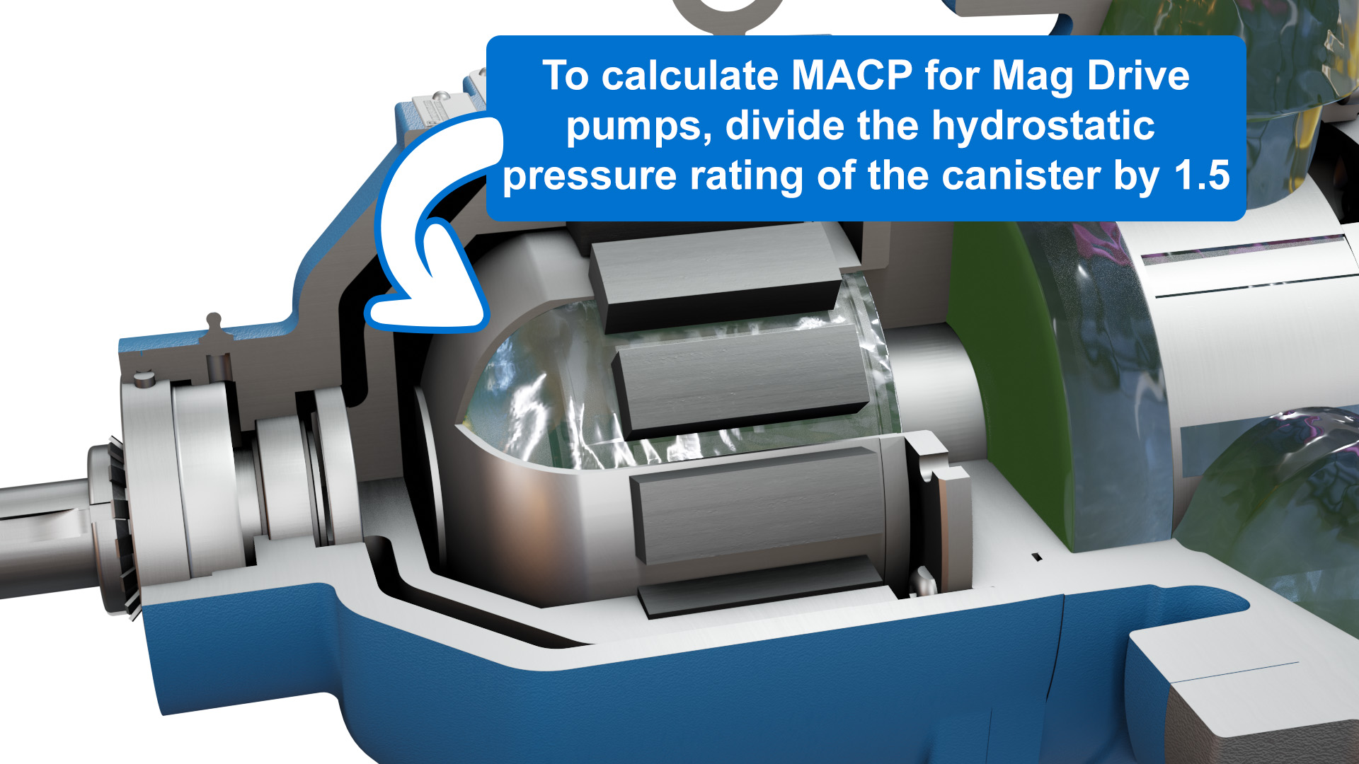
Maximum allowable casing pressure (MACP) can be established as the pressure limit of the port connections for most pump models. In the case of Mag Drive pumps, it can be considered as the hydrostatic limit of the canister divided by 1.5.
What is maximum allowable casing pressure (MACP)?
Maximum allowable casing pressure is the maximum rated pressure of the pressure containing components of the pump. This rating does not include the seal. However, this rating does include the canister in Mag Drive pumps.
Converting PSI to Kilopascals
PSI / 0.145 = kPa
Converting kilopascals to PSI
A kilopascal (kPa) is equivalent to around 0.145 pounds per square inch (PSI).
kPa x 0.145 = PSI
What is a kilopascal?
The “kilopascal” is a common unit of pressure and is equivalent to 1,000 pascals. The pascal is named after the French mathematician Blaise Pascal.
Where is inlet pressure measured?
Measurements can be made at the gauge port on the inlet side of the pump or at a point on the inlet pipe as close as possible to the pump.
What is inlet pressure?
Inlet pressure is the amount of pressure measured at the inlet port of a pump. Common units of measure include, pounds per spare inch (PSI) or bar. The measured value can be positive or negative.
What is a hydrostatic pressure test used for?
A hydrostatic pressure test is used to check the integrity of a pump’s casting, seal, and gasket/s.
What is the hydrostatic test pressure?
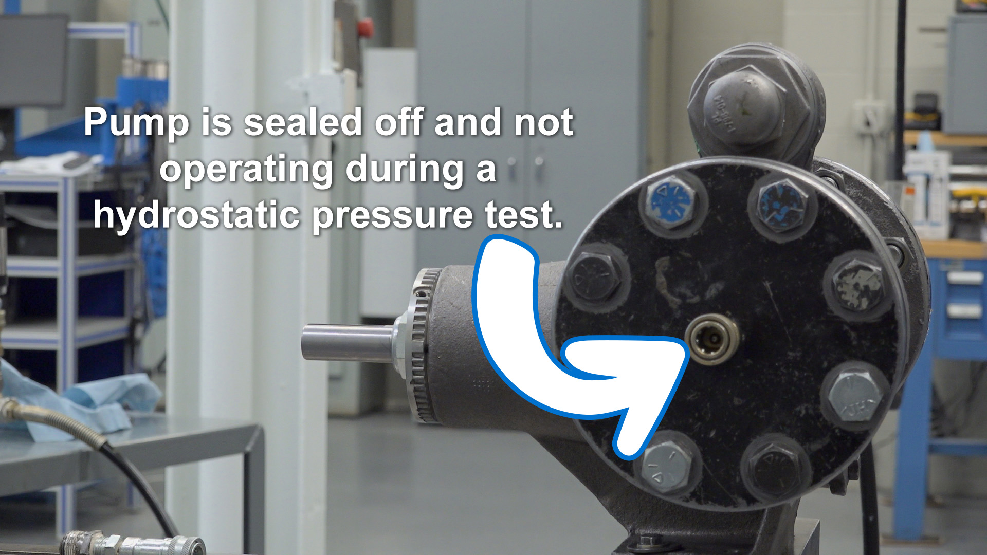
Hydrostatic test pressure is the pressure to which the pump will be subjected to for a short duration to ensure casting, seal, and gasket integrity. This is achieved by sealing and pressurizing the pump when it is not in operation. Hydrostatic test pressures can be to as much as 1.5 times the maximum allowable working pressure, but may be limited by other factors such as the seal.
How to calculate the relief valve full bypass pressure
This value is entirely dependent on the valve being used, the spring in the relief valve, and the capacity of the pump.
What is full bypass pressure?
Full bypass pressure is the pressure at which the entire capacity of a pump is bypassing through the relief valve. In other words, this is the maximum differential pressure rating for pumps with internal relief valves or the maximum discharge pressure rating for pumps with return-to-tank valves or in-line system valves.
Where is discharge pressure measured?
Measurements can be made at the gauge port on the outlet side of the pump or at a point on the outlet piping as close as possible to the pump.
What is discharge pressure?
Discharge pressure is the amount of pressure measured at the outlet port of a pump. This can also be known as outlet pressure or discharge head. Common units of measure include pounds per spare inch (PSI) or bar.
Can differential pressure be negative?
Yes! For example, a pump is at the bottom of a very tall, very full tank and the pump has a very short discharge pipe. The head pressure acting on the pump's inlet side may be greater than the discharge pressure due to viscous line losses. In this scenario you could omit the pump and let gravity empty the tank but a pump can expedite this and allows you to control the rate of flow.
How do you calculate differential pressure?
Differential pressure is a function of the system and must be calculated or measured. Measurements can be made at the gauge ports near the inlet and outlet ports of the pump.
Differential Pressure = (Outlet Pressure) – (Inlet Pressure)
What is differential pressure?
Differential pressure, otherwise known as total dynamic head, is the difference between the discharge pressure and the inlet pressure.
How to calculate the appropriate relief valve cracking pressure
This value can be given by the user or established at 10-15% above the maximum differential pressure for pumps with internal relief valves or the maximum discharge pressure for pumps with return-to-tank valves or in-line system valves.
What is cracking pressure?
Cracking pressure is the pressure level at which a pump relief valve begins to open and bypass liquid.
How to convert bar to PSI?
Bar x 14.504 = PSI
Units of Pressure: What does “bar” mean?
Bar is a metric unit of pressure measurement that is equal to 100,000 pascals (100 kPa). One bar is slightly less than one atmosphere.
1 bar = 0.987 atm
Other units that are derived from the bar include:
Megabar = 1,000,000 bar
Kilobar = 1,000 bar
Decibar = 0.1 bar
Centibar = 0.01 bar
Converting PSI to atmospheres
PSI / 14.7 = atm
Converting atmospheres to PSI
An atmosphere (atm) is equivalent to around 14.7 pounds per square inch (PSI).
Atm x 14.7 = PSI
Units of Pressure: What is an atmosphere?
When talking about pumps and pressure, the term “atmospheres” is a common unit of measure. It is based on atmospheric pressure at sea level.
Which hygienic pump is best for high pressure?
The Viking hygienic pump with the highest pressure rating is our TRA®20 Series at 500 PSI. We encourage potential customers to contact their local distributor to discuss your specific application needs.
Pump Types
How do external gear pumps work?
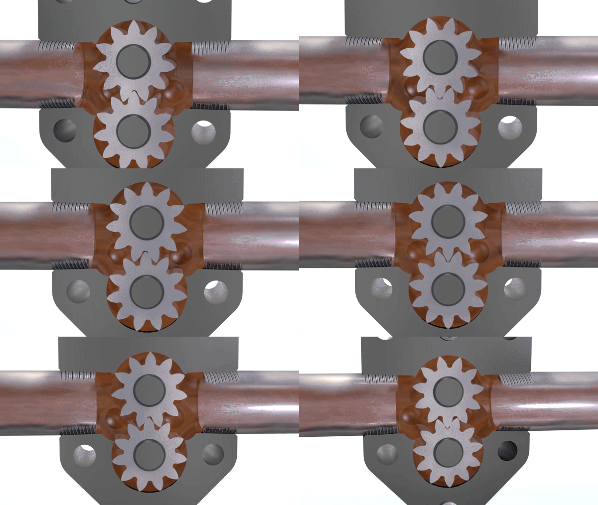
External gear pumps are similar in pumping action to internal gear pumps in that two gears come into and out of mesh to produce flow. However, external gear pumps use two identical gears rotating against each other. One gear is driven by the motor (driver gear) while the other (driven) gear meshes with and is rotated by the driver gear.
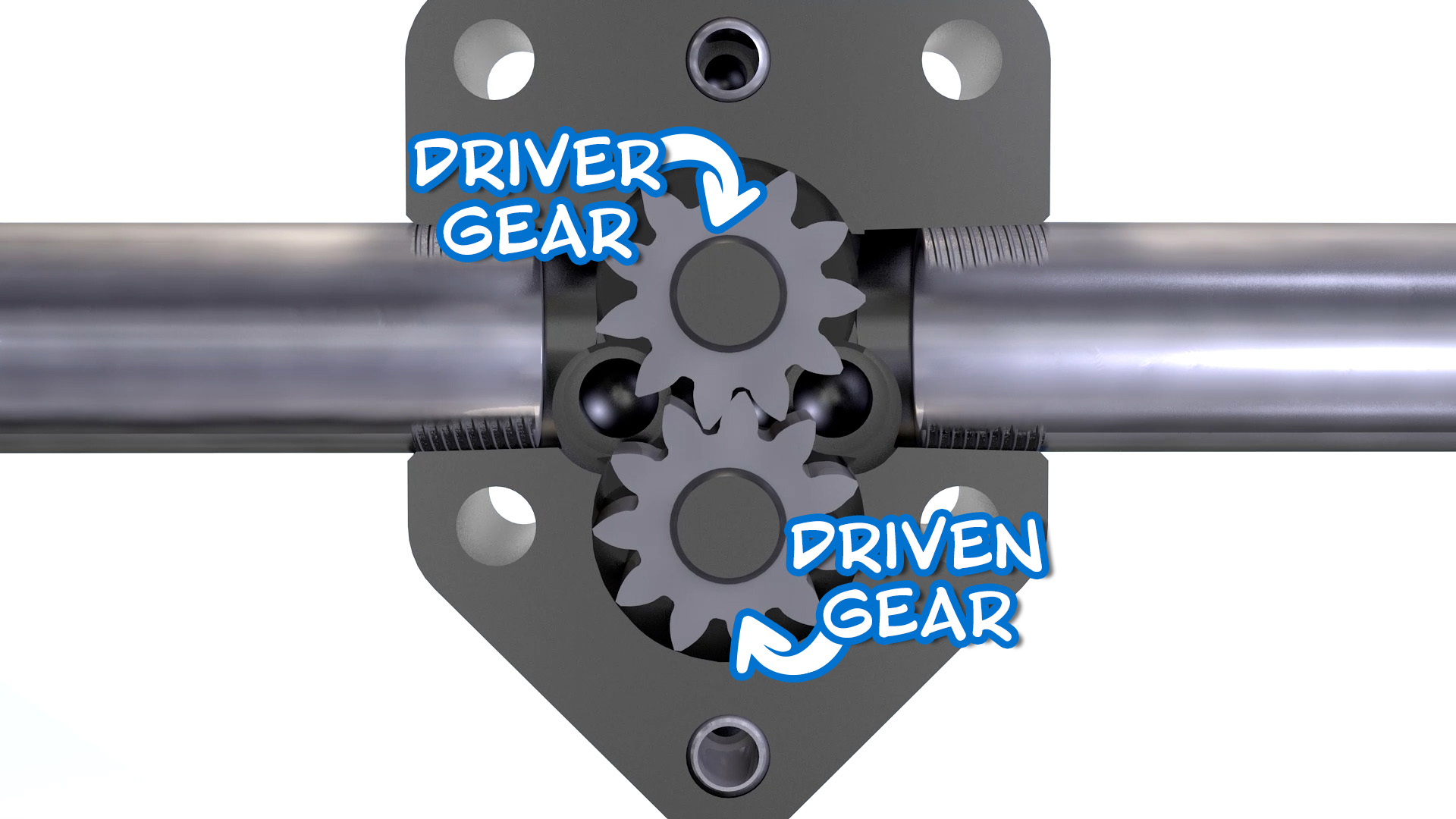
As the gears come out of mesh, they create an expanding volume on the inlet side of the pump. This creates a vacuum which pulls liquid into the pump. Liquid is trapped between the gear tooth cavities and the close fitting casing wall. The rotation of the gears carries the liquid around to the outlet side of the pump. The liquid does not pass between the gears. At the outlet, the meshing of the gears forces the liquid through the outlet port.
What is a GP pump?
The GP Series is an obsoleted series of external gear pumps which has been largely replaced by the SG Series™.
What are internal gear pumps used for?
Internal gear pumps are used in a wide variety of applications because they're suitable for a wide range of viscosities and come in a variety of sizes and constructions. Some of the most common applications include asphalt, adhesives, and chocolate.
What are vane pumps used for?
Since vane pumps have sliding vanes that run in contact with the casing wall, they are commonly used in thin liquid applications like solvents, alcohols, and various acids or bases.
How does a vane pump work?
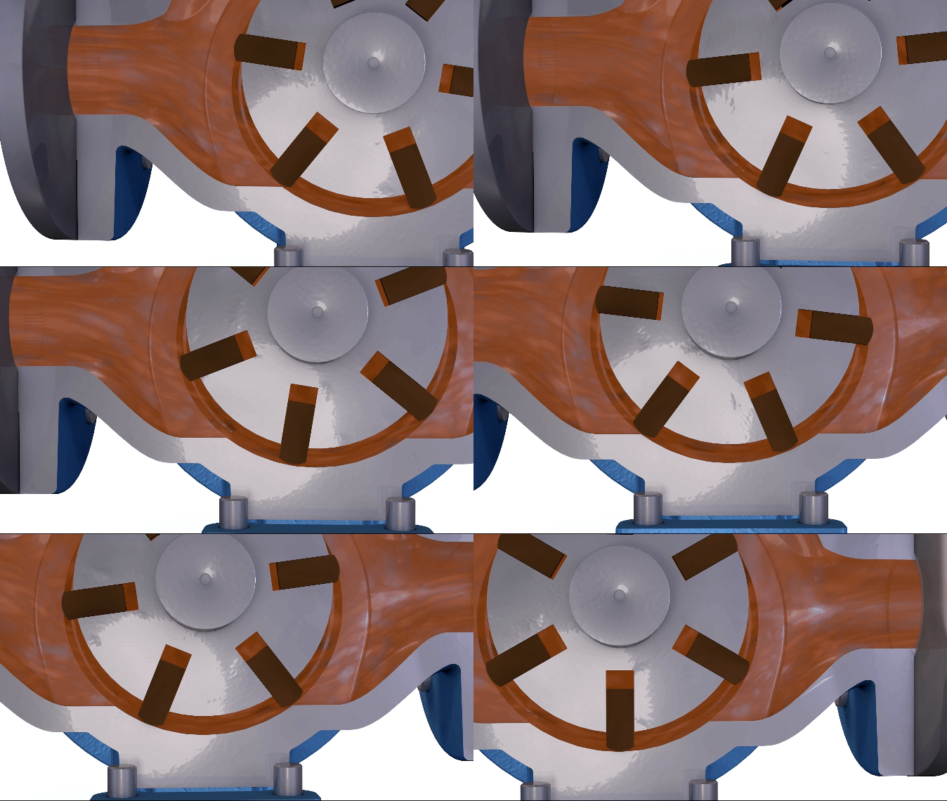
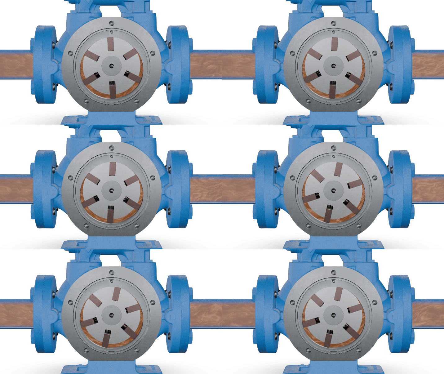
Vane pumps move fluid using the rotary motion of multiple sliding vanes. Vane pumps consist of a slotted rotor rotating inside a cam shaped housing. This rotor is located close to the wall of the cam so that a crescent-shaped cavity is formed on the opposite wall.
Each rotor slot contains a sliding vane. As the rotor rotates, centrifugal force, hydraulic pressure, and push rods work together to extend each vane to the casing wall. This creates an expanding cavity on the inlet side – creating a vacuum which pulls liquid into the pump. Liquid is trapped between the vanes and the casing wall. The rotor rotation moves the liquid cavities around to the outlet side of the pump.
At the outlet side, the vanes are forced back into their slots, decreasing the cavity size and forcing the liquid through the outlet port.
What is a vane pump?
Vane pumps are a type of rotary positive displacement pump consisting of a slotted rotor offset in a cam shaped housing. Sliding vanes in the slots of the rotor extend to create pumping cavities, sweep the liquid through the casing, and expel the liquid at the discharge side of the pump as the cam reduces in area and forces each vane back into its slot. Click here to view our How it Works video on this topic.
How do Universal mag drive pumps work?
At the core of Universal mag drive pumps is the magnetic coupling. There are two assemblies that contain an equal number of magnets with alternating poles. The first, inner magnet assembly, connects directly to the pump shaft while the second outer magnet assembly is driven by the motor. The attraction of opposing polarity magnets align the inner and outer magnet assemblies, which in turn enables the rotating outer magnet to transmit its rotation to the inner magnet and pump shaft assembly. This then rotates the pump internals, creating flow.
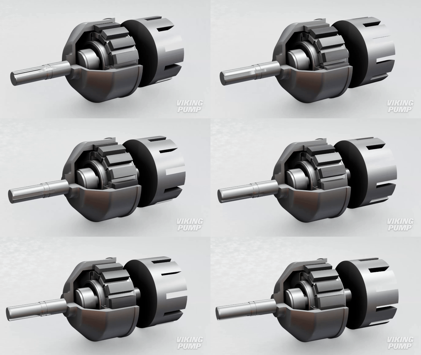
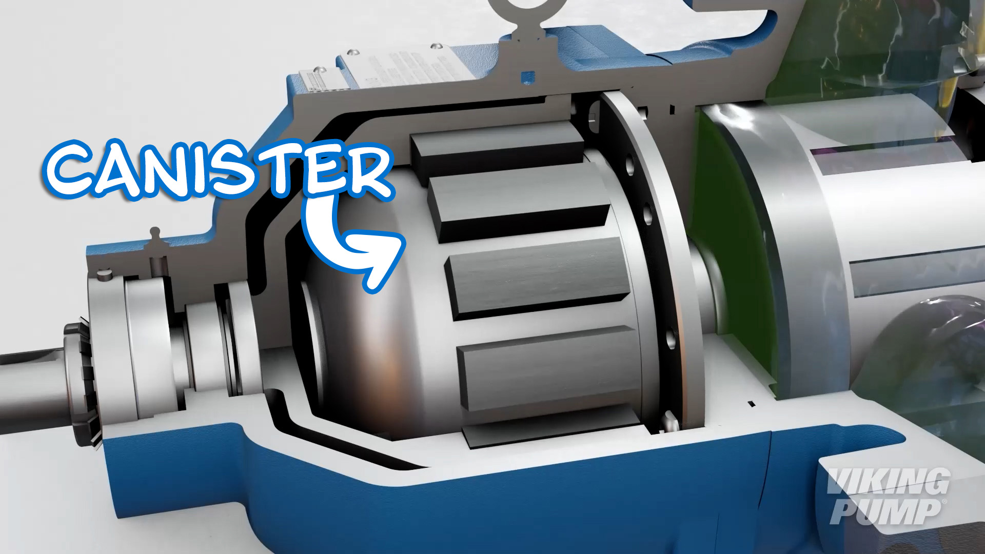
A containment shell - called a canister - fits around the inner magnet, keeping the liquid inside the pump without the use of a dynamic seal.
What is a universal mag drive pump?
Viking Pump’s Universal Mag Drive is a series of sealless mag drive internal gear pumps. They are named as such due to their shared dimensions with comparable sized Viking product series in the Universal product line.
Click here to view a video about Viking Pump’s Universal Mag Drive product series.
What is a spur gear pump?
Spur gear pumps are a series of Viking Pump external gear pumps named such due to the cut of the external gears. This series is referred to as the SG Series™.
Spur gear, or external gear, pumps are a type of rotary positive displacement gear pump that features two identical external gears where one gear is the drive gear and one is the driven. The liquid is transferred from between the gear teeth by the rotation of the pump. Click here to view a video on this subject.
What are lobe pumps used for?
Because of the large pumping cavities and non-contacting design, lobe pumps are ideal for the gentle handling of both thin and viscous liquids and liquids containing large solids. They are designed to be easily cleaned, making them ideal for applications requiring sanitary construction and frequent cleaning -this includes clean-in-place (C.I.P.) and steam-in-place (S.I.P.) processes.
How do lobe pumps work?
Lobe pumps are similar in pumping action to external gear pumps but differ in that the rotors are driven independently on 2 rotating shafts. A pair of external timing gears ensure that the rotors do not contact.
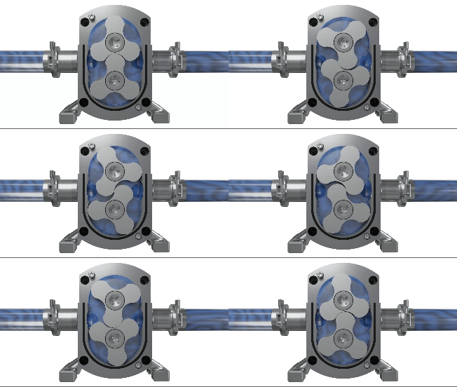
As the rotors turn, a cavity is formed at the inlet side of the pump. This creates a vacuum to pull the liquid into the spaces between the tips of the lobes. This liquid is trapped between these lobes and the close-fitting casing wall. The rotation of the rotors carries the liquid around to the outlet side of the pump. The liquid does not pass between the rotors.
At the outlet, the meshing of the lobes forces the liquid through the outlet port.
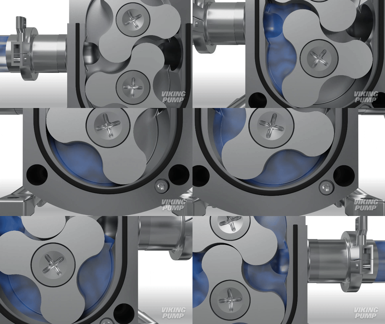
What is a lobe pump?
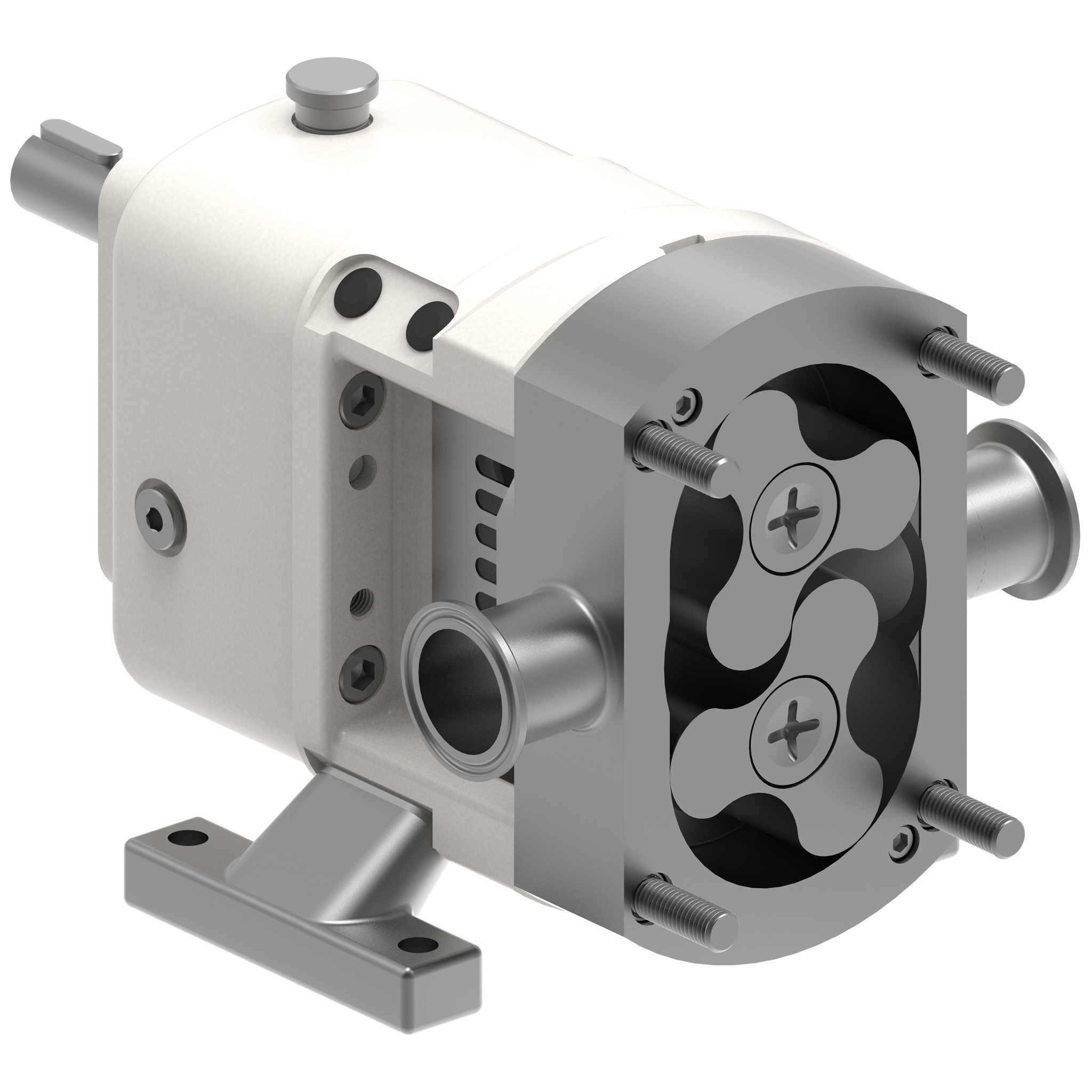
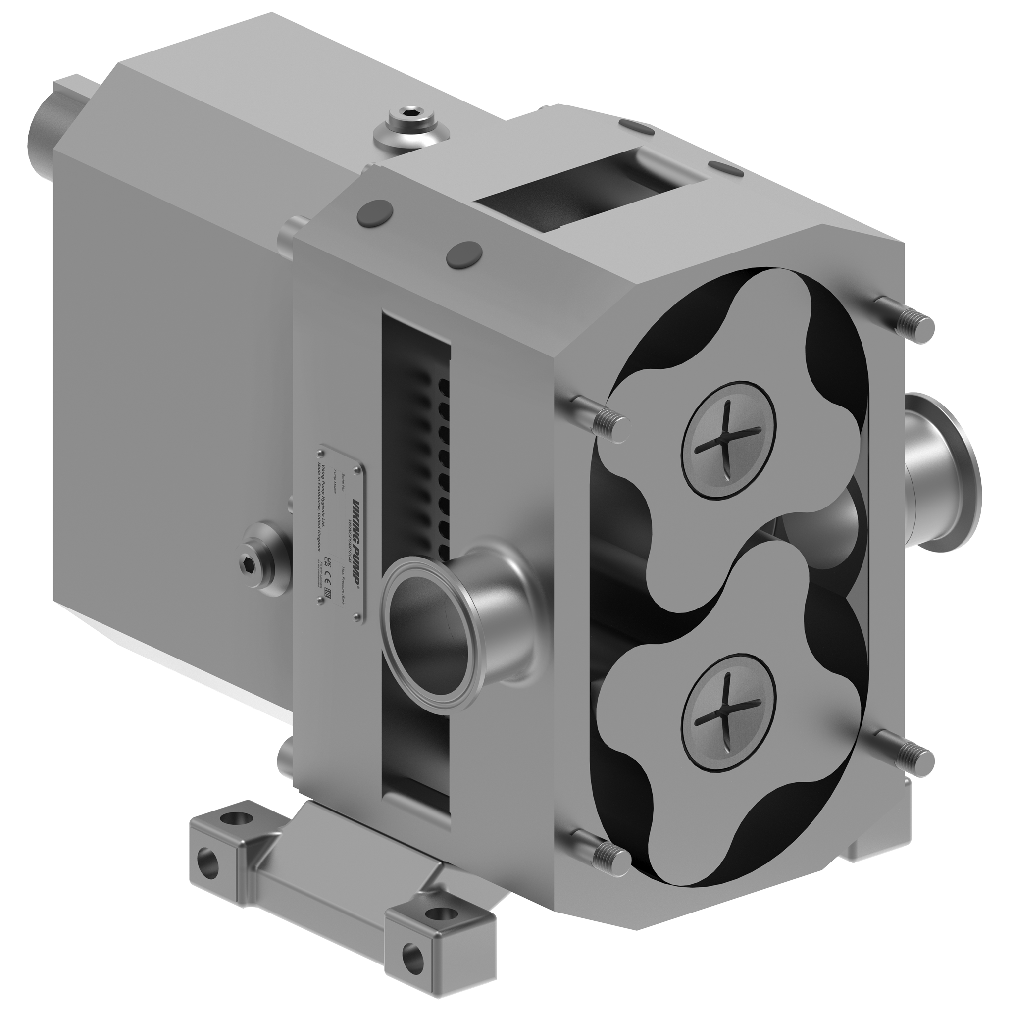
Lobe pumps are a type of rotary positive displacement pump that consists of a pair of externally timed rotors. Each rotor is driven independently on a separate shaft. The rotors are non-contacting. Rotor designs vary but some of the more common types include tri-lobe and multilobe designs. Lobe pumps operate similarly to circumferential piston pumps. Click here to view our How it Works video on this topic.
 |
 |
|---|
How do internal gear pumps work?
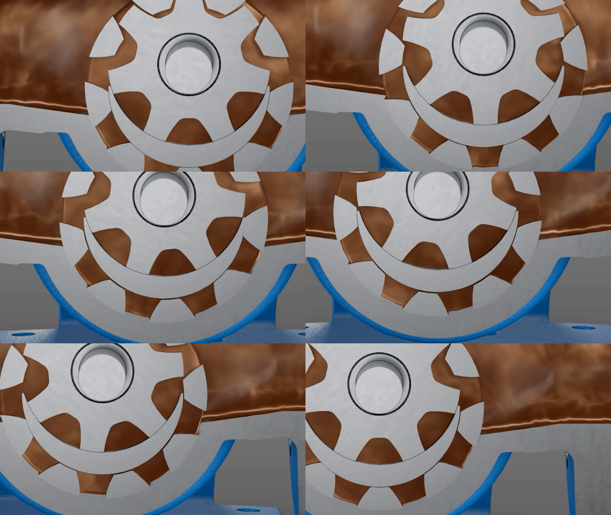
The internal gear pump is a rotary positive displacement pump that moves fluid using the rotary motion of the pumping elements. Liquid enters the suction port between the teeth of the rotor gear - the larger exterior gear, and the idler gear - the smaller interior gear. The intermeshing gears of the rotor and idler form locked cavities for the liquid to ensure volume control.
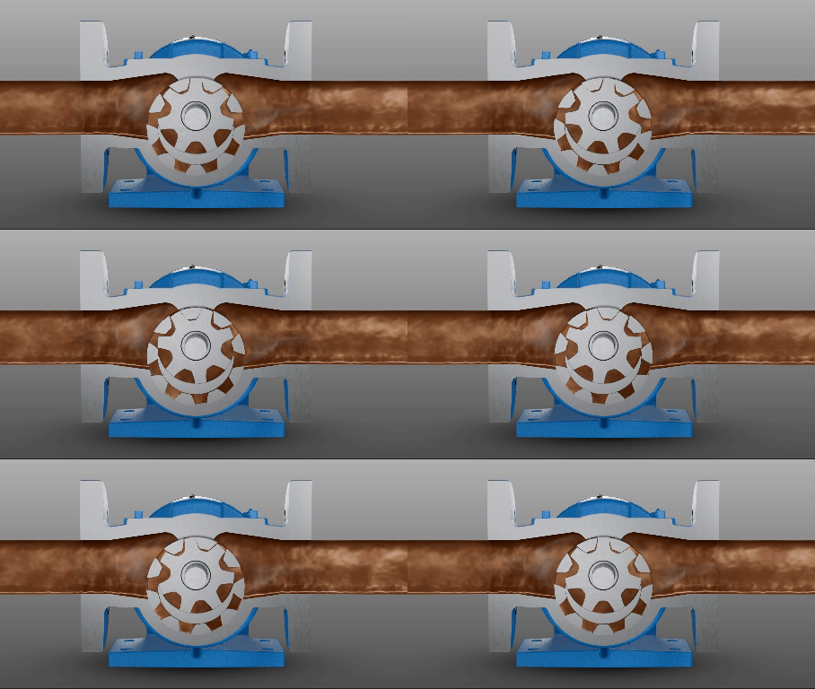
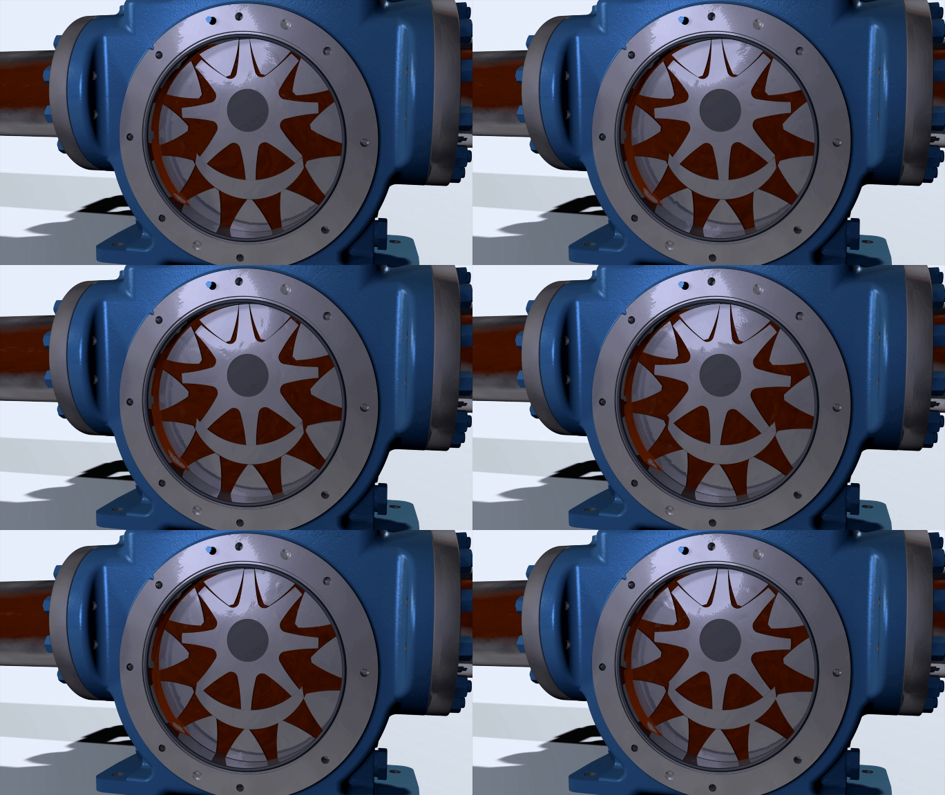
As the teeth come out of mesh, low pressure zones are created at the suction port, pulling liquid into the spaces. The liquid continues to travel through the pump, between the teeth of the gear-within-a-gear principle. Liquid is prevented from returning to the suction side by the crescent located on the head of the pump, acting as a seal between the suction and discharge ports.
When the teeth mesh completely, liquid is forced out of the spaces and out of the discharge port.is rotated by the driver gear.
As the gears come out of mesh, they create an expanding volume on the inlet side of the pump. This creates a vacuum which pulls liquid into the pump. Liquid is trapped between the gear tooth cavities and the close fitting casing wall. The rotation of the gears carries the liquid around to the outlet side of the pump. The liquid does not pass between the gears. At the outlet, the meshing of the gears forces the liquid through the outlet port.
What are gerotor pump used for?
The gerotor pump is efficient, compact, and quiet. The simple design, with few moving parts, is ideal for a wide variety of applications including hot cooking oil filtration and automotive applications like fuels, lube oils, and transmission fluids.
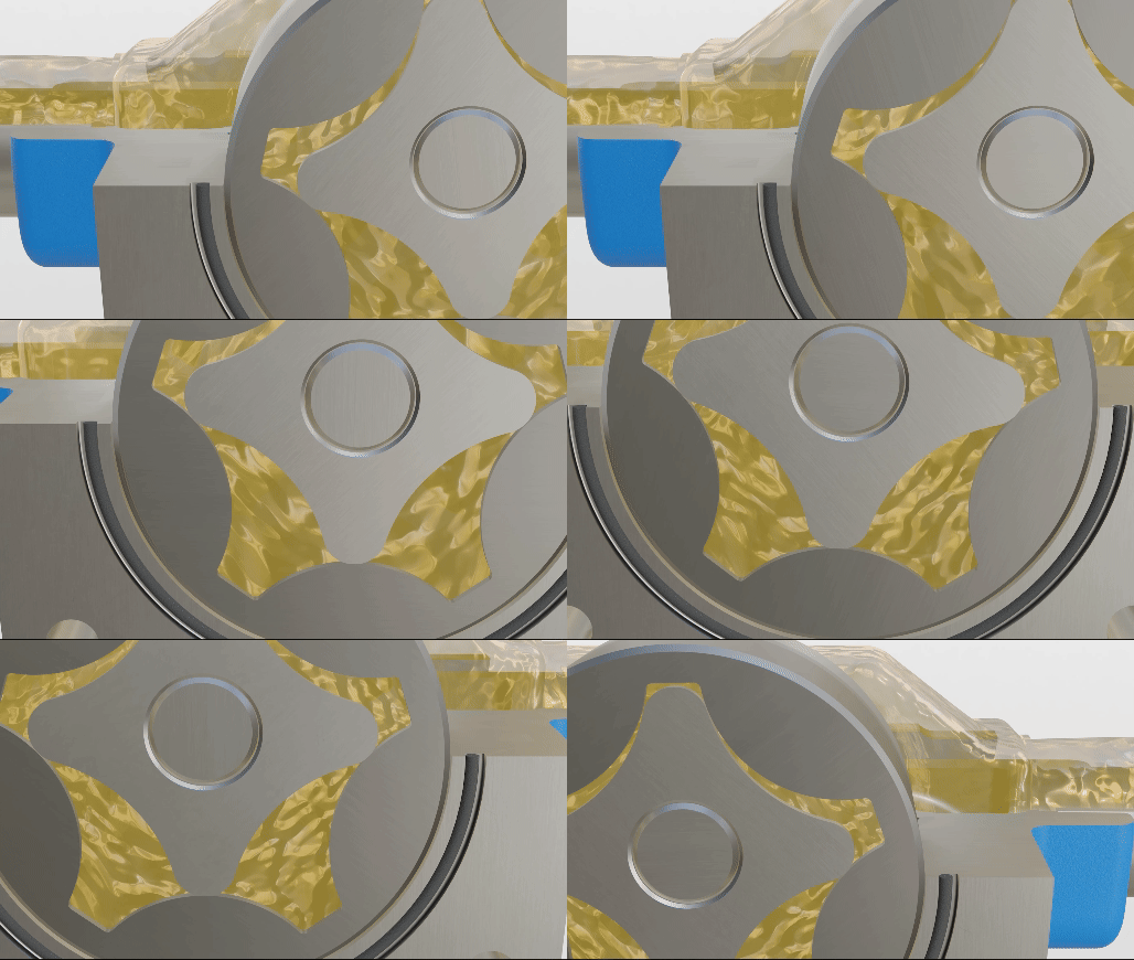
How does a gerotor pump work?
In a gerotor pump, liquid enters the suction port between the teeth of the elements. There is a smaller, inner, driver element…and a larger, outer, driven element. While tooth counts vary, the outer element has one more tooth than the inner element, creating cavities between the teeth. As the pump rotates, these cavities expand on the inlet side and contract on the outlet side.
As the teeth come out of mesh, a low-pressure zone is created at the suction port, pulling liquid into the spaces. The liquid continues to travel through the pump, between the teeth of the gear-within-a-gear principle. Liquid is prevented from returning to the suction side due to the close tolerance of the gears, acting as a seal between the suction and discharge ports. When the teeth mesh completely, liquid is forced out of the spaces and out of the discharge port.
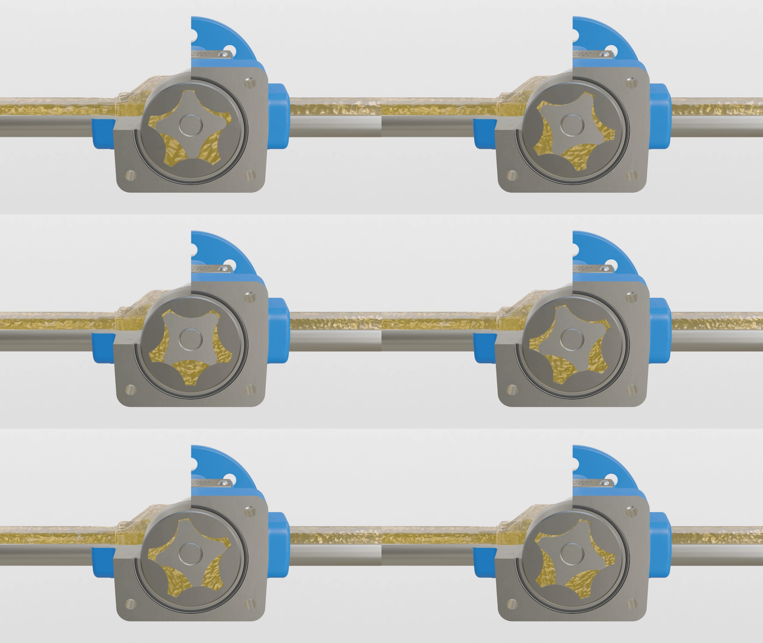
What is a gerotor pump?
A type of internal gear pump that is driven by the idler gear and does not include a crescent. Click here to view our How it Works video on this topic.
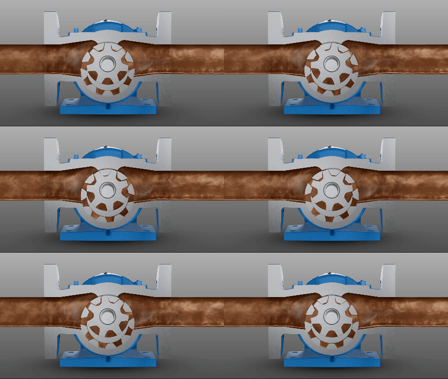
What is an internal gear pump?
A type of gear pump with a drive gear featuring inward facing teeth called a rotor. This rotor turns an offset gear with fewer outward facing teeth called an idler. A crescent shape protruding from the head of the pump creates this offset and seals the pumping cavities formed between the gear teeth. Click here to view our How it Works video on this subject.
What are the different types of gear pumps?
Again, common types of gear pumps include rotary positive displacement pumps like the internal gear, external gear, and gerotor pumps.
What is a gear pump?
A gear pump is any type of rotary positive displacement pump consisting of gears where the pumping results from the unmeshing and remeshing of gears. The liquid is carried between the gear teeth by the rotation of the pump. Common types of gear pumps include internal gear, external gear, and gerotor.
What applications may require an eXtreme positive displacement pump?
Since the eXtreme positive displacement pump (XPD) meets API 676 standards, these pumps are well suited for oil and gas applications, refineries, petrochemical processes, and industrial markets for a variety of applications.
How does an an eXtreme positive displacement pump work?
An eXtreme positive displacement pump works like any other internal gear pump that Viking Pump offers.
Liquid enters the suction port between the teeth of the rotor gear, which is the larger exterior gear, and the idler gear, the smaller interior gear. The meshing gears of the rotor and idler form locked cavities for the liquid to ensure volume control.
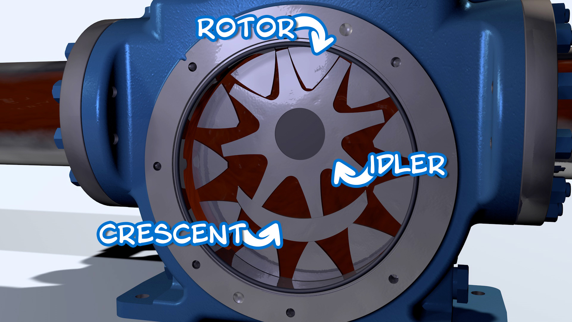
As the teeth come out of mesh, low pressure zones are created at the suction port which pulls liquid into the spaces. The liquid is trapped between the teeth of the gear-within-a-gear principle and continues to travel through the pump.
Liquid is prevented from returning to the suction side by the crescent located on the head of the pump, acting as a seal between the suction and discharge ports. When the teeth mesh completely, liquid is forced out of the spaces and out of the discharge port.
What is an eXtreme positive displacement pump?
An eXtreme positive displacement pump (XPD) is a series of Viking Pump internal gear pumps that are constructed to be fully compliant with API 676 requirements, documentation, and testing.
To learn more, watch this video.
What are external gear pumps used for?
Since external gear pump gears are supported on both sides, these gear pumps are routinely used for high-pressure applications including hydraulics and pipeline injection. They can come in many sizes to accommodate a wide variety of high speed, high pressure applications.
What is an external gear pump?
External gear pumps are a type of rotary positive displacement gear pump that features two identical external gears where one gear is the drive gear and one is the driven. The liquid is transferred from between the gear teeth by the rotation of the pump. Click here to view a video on this subject.
Servicing a composite mag drive pump
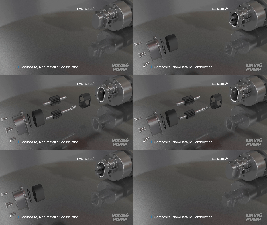
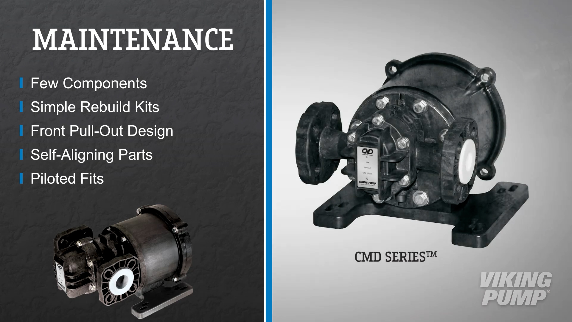
Composite mag drive pumps like the CMD Series™ have very few components, rebuild kits, and a front pull out design – so maintenance is relatively easy. Self-aligning parts and piloted fits ensure proper assembly.
What do you use a composite mag drive pump for?
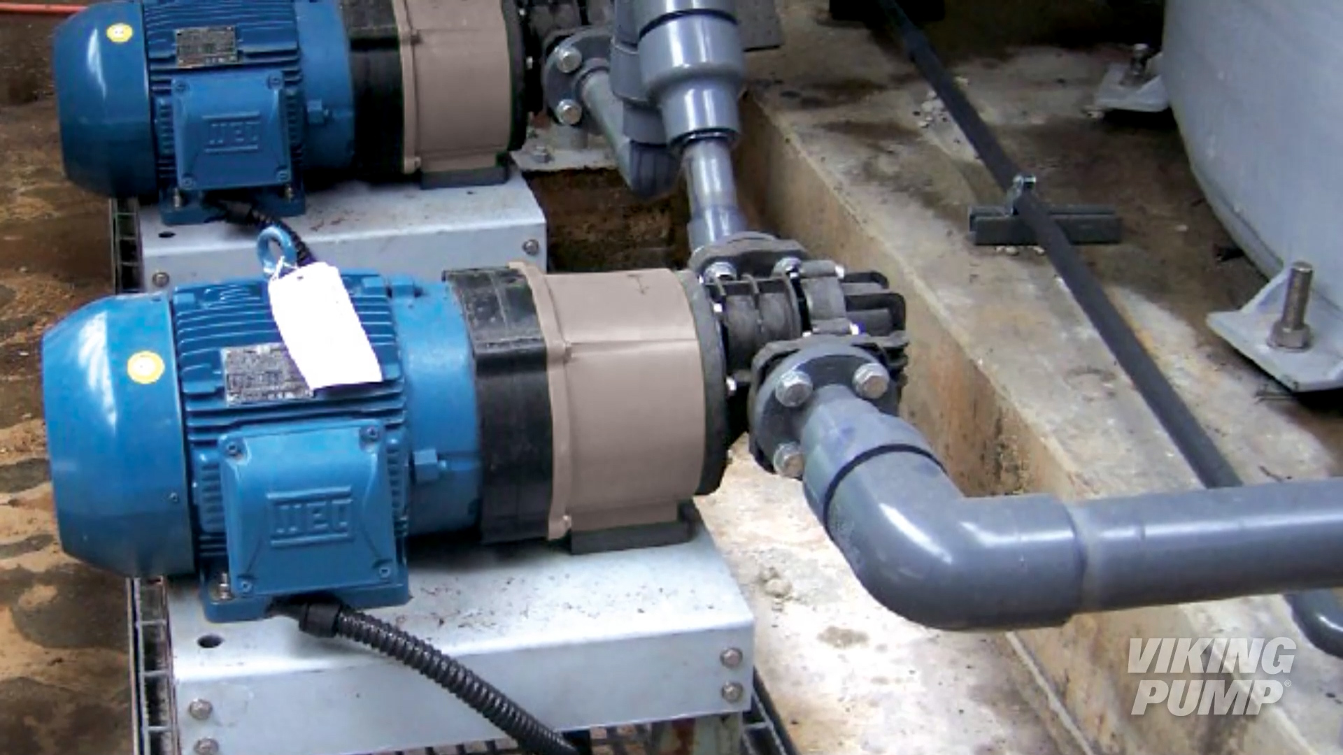
Because of their non-metallic construction, composite mag drive pumps are ideal for industrial chemical metering and industrial waste water management. These applications require pumps that can handle harsh or dangerous chemicals and can dose them in exact quantities. Specific markets include the chemical metering for biofuels, mining, food additives, and foundry applications.
What is a composite mag drive pump?
A composite mag drive pump is a sealless, magnet driven external gear pump (the Viking Pump® CMD Series™) that has non-metallic, composite construction.
What are circumferential piston pumps used for?
Since circumferential piston pumps have such large pumping cavities and a non-contacting design, these pumps are ideal for thin and viscous liquids as well as liquids containing large solids. They can be easily cleaned, making them ideal for applications requiring sanitary construction and frequent cleaning.
How do circumferential piston pumps work?
Despite the name, pistons have nothing to do with this pump’s operation. Like a gear pump, two rotors rotate in a close fitting housing – however, the rotors are driven independently on two rotating shafts. External timing gears ensure that the rotors do not contact.
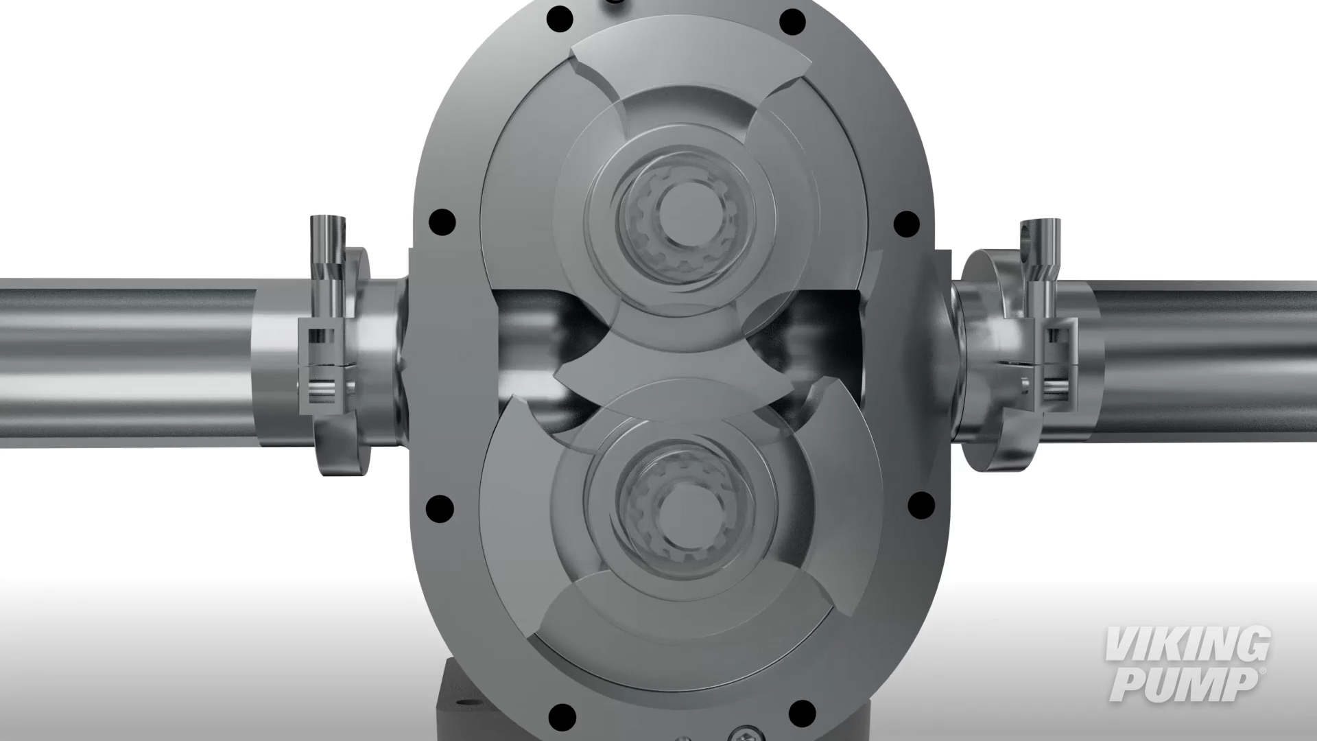
As the rotors rotate, a cavity is formed at the inlet side of the pump – creating a vacuum that pulls liquid into the spaces between the tips of the rotor.
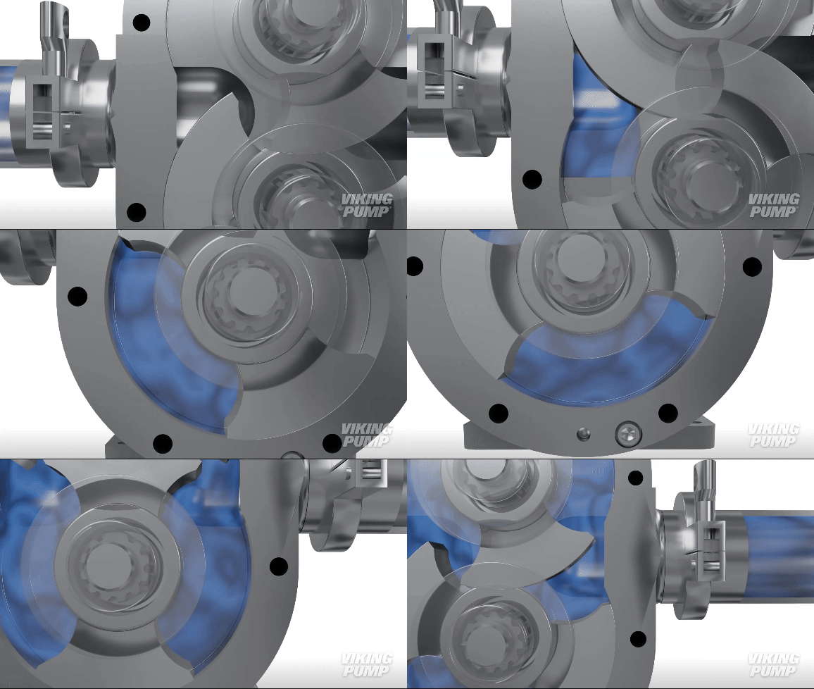
The liquid is trapped between the rotor and casing wall – and is carried around to the outlet. The tight clearance between the outside of the rotor and the hub of the other rotor ensures liquid does not pass between them.
At the outlet the reduction in size of the pumping cavity forces liquid through the outlet.
What is a circumferential piston pump?
Circumferential piston pumps (or external circumferential piston pumps) are a type of rotary positive displacement pump consisting of a pair of externally timed rotors such that each is driven independently and the rotors are non-contacting. Rotor designs vary but the most common type is bi-wing. These pumps are similar in operation to a lobe pump. Click here to view a video on this subject.
What are centrifugal pumps used for?
Centrifugal pumps are widely used in a number of applications – including water supply or treatment systems, irrigation, and chemical processing.
How do centrifugal pumps work?
By design, centrifugal pumps operate in one direction of rotation and one direction of flow. Liquid enters the suction port, through the eye on an impeller and is pushed out radially toward the discharge port.
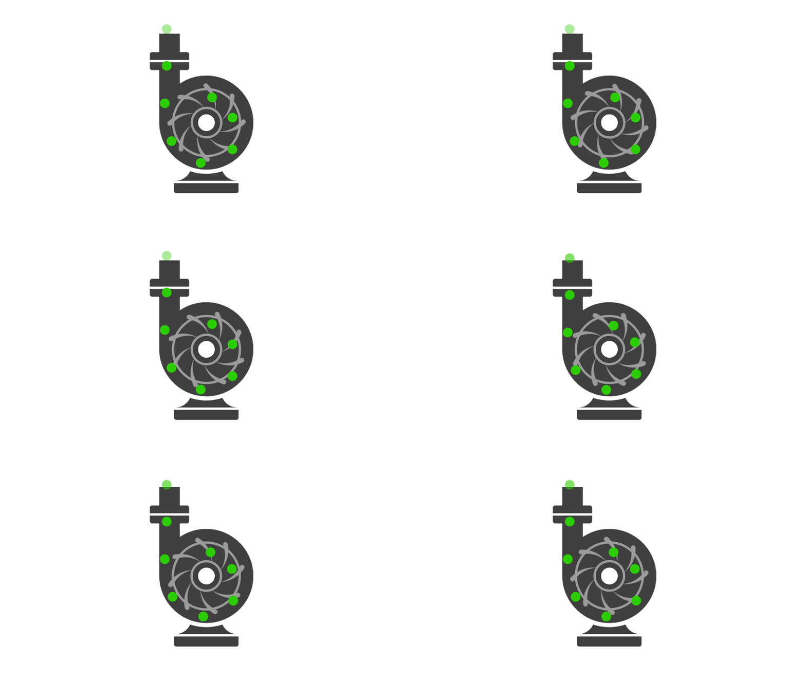
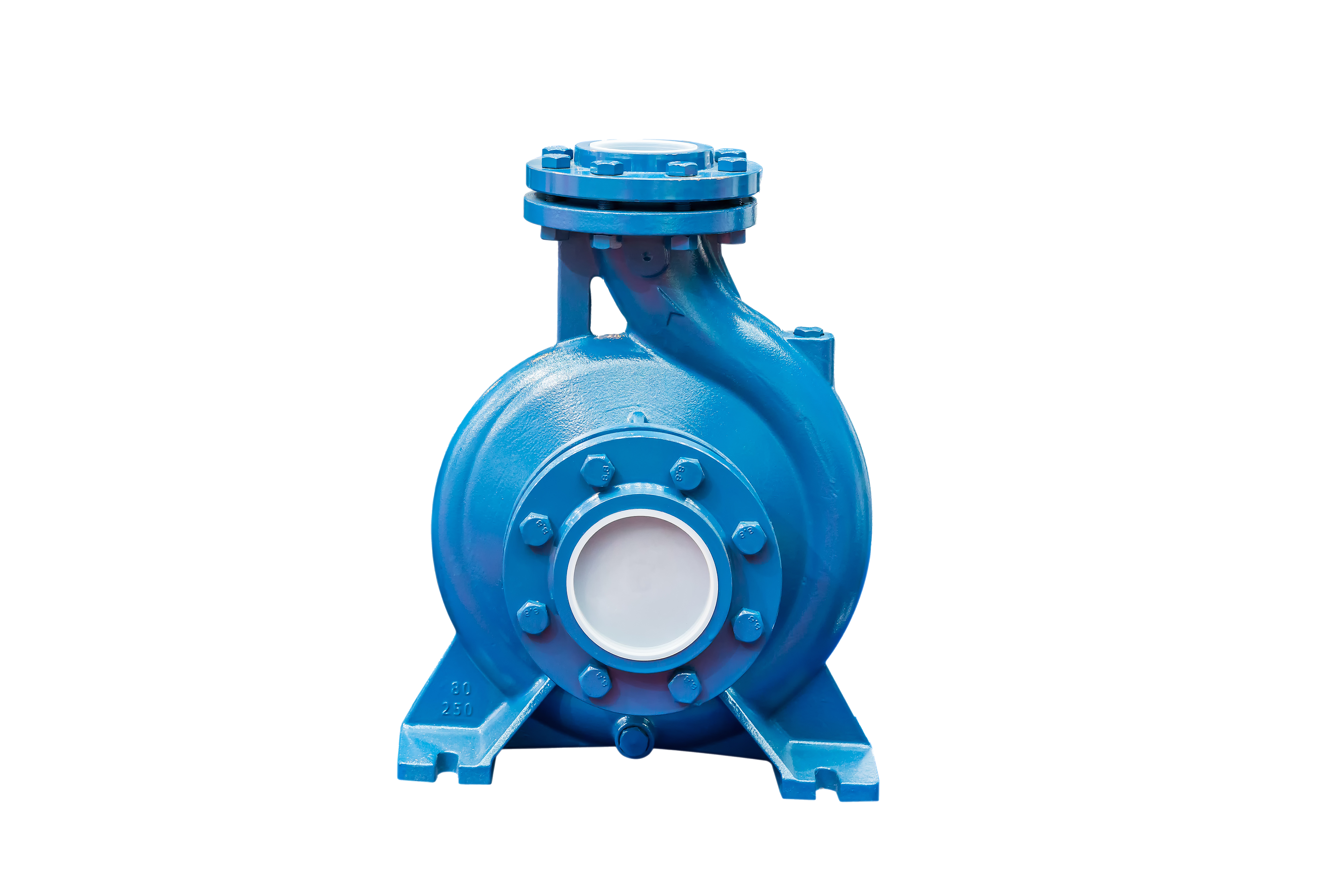
What is a centrifugal pump?
A type of kinetic pump consisting of a rotating impeller in a casing volute. This type of pump transfers rotational energy from a spinning impeller to the liquid.
How are rotary lobe & circumferential piston pumps different than peristaltic pumps?
Peristaltic pumps certainly have their place in the hygienic process, especially when handling fluids that will be infused with someone's blood (like IV fluid, for example). However, there are phases of the hygienic process that require gentle handling of the fluid being conveyed and the pulsation of a peristaltic pump could damage the product. That is why having a RL or CPP with consistent speed and flow is ideal, depending on the phase of production of the liquid.
How are a rotary lobe & circumferential piston pumps different from centrifugal pumps?
Centrifugal pumps can transfer large volumes of liquid, but efficiency and flow decrease rapidly as pressure and/or viscosity increases. Rotary pumps and circumferential piston pumps, on the other hand, offer higher efficiency wherein they move a consistent amount of liquid at a constant speed. They are gentle on liquids and have extremely low shear characteristics across a wide range of product viscosities.
What are the advantages of a rotary lobe pump?
Rotary lobe pumps are the mainstay of many hygienic fluid handling applications where gentle handling & cleanability are of utmost importance. These pumps have a wide range of displacements, good solids handling capabilities, and low shear characteristics across a wide range of product viscosities. The non-contacting pumping principle for RLPs means no metal-on-metal contact, limiting pump wear regardless of product viscosity.
What are the advantages of a circumferential piston pump?
Circumferential piston pumps handle high value shear sensitive liquids across hygienic applications where gentle handling, cleanability, and efficiency are paramount. Viking Pump Hygienic has a wide range of displacements with high pressure capabilities. It's ability to handle solids is excellent and has low shear characteristics across a wide range of product viscosities.
What is a hygienic pump?
A hygienic pump is used in systems where cleanliness is vital to the product being pumped, such as food products, beverages, and pharmaceuticals. Hygienic pumps need to be able to be cleaned and sanitized on a regular basis and must be able to handle liquids gently. Indications that a pump is considered hygienic include certification of being an ATEX pump as well as other certifications.
Aren't PDP pumps prone to leaking?
Many of our models come with our patented O-Pro® Seal which dramatically reduces leaks. O-Pro® Seals utilize a series of O-rings to create a robust seal and lubrication chamber, all in one. O-Pro® Barrier seal functions as both a seal and bracket bushing; O-Pro® Cartridge & Guard seals are simple retrofit options. This means a safe, clean environment for your staff and money saved from lost product.
What are industrial pumps?
Industrial pumps are pumps used in more general applications like all varieties of refined fuels & lubricants, resins & polymers, alcohols & solvents, asphalt & bitumen, polyurethane foam, food products, paints & inks, soaps & surfactants, and heat transfer fluids.
How do industrial pumps work?
Viking Pump's positive displacement pumps displace liquid with each revolution of the internal pumping elements. This is done by trapping liquid between the pumping elements and a stationary casing. Depending on the application, a pump may need to be jacketed or electrically heated in order to keep a warm ambient temperature inside the pump to prevent the product from solidifying.
Seals
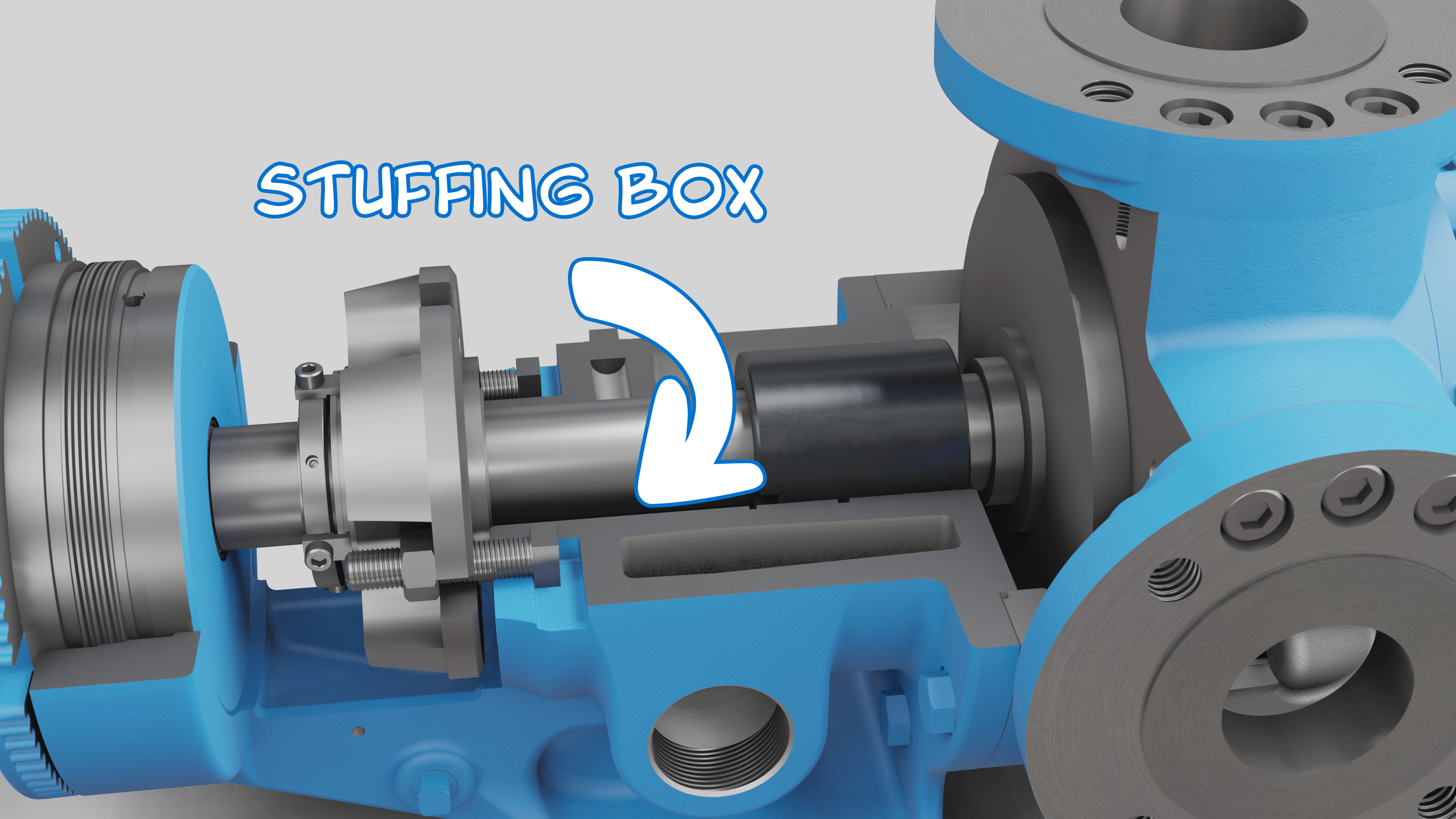
What is a pump stuffing box?
In pumps, the stuffing box is the hollow space where the rotating shaft enters the stationary pump housing. While the term originated from shaft packing that was “stuffed” around the shaft to create a seal, today a pump’s stuffing box can be fitted with a mechanical seal, lip seal, or O-Pro® seal instead of packing.
How sealless mag drive pumps work?
At the core of sealless mag drive pumps is the magnetic coupling. There are two assemblies that contain an equal number of magnets with alternating poles. The first, inner magnet assembly, connects directly to the pump shaft while the second outer magnet assembly is driven by the motor. The attraction of opposing polarity magnets align the inner and outer magnet assemblies, which in turn enables the rotating outer magnet to transmit its rotation to the inner magnet and pump shaft assembly. This then rotates the pump internals, creating flow.
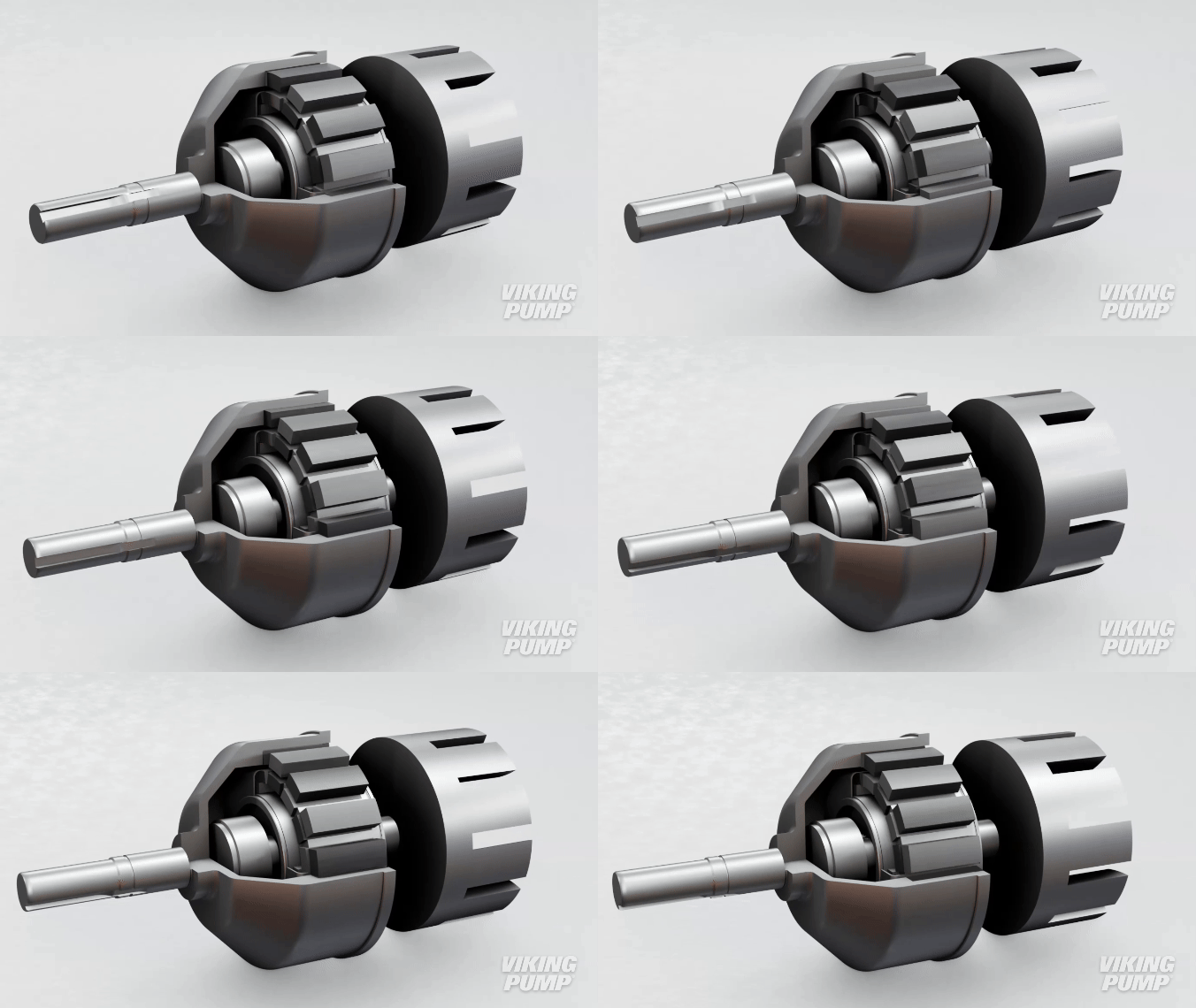
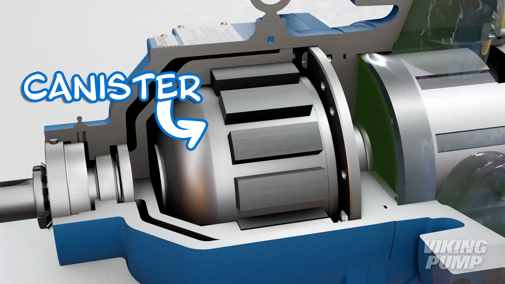
A containment shell - called a canister - fits around the inner magnet, keeping the liquid inside the pump without the use of a dynamic seal.
What are sealless mag drive pumps used for?
Sealless mag drive pumps offer the highest level of liquid containment and are favored in applications that are difficult to seal, pose environmental or health risks, or where the longest possible seal life is desired.
What is sealless mag drive pump?
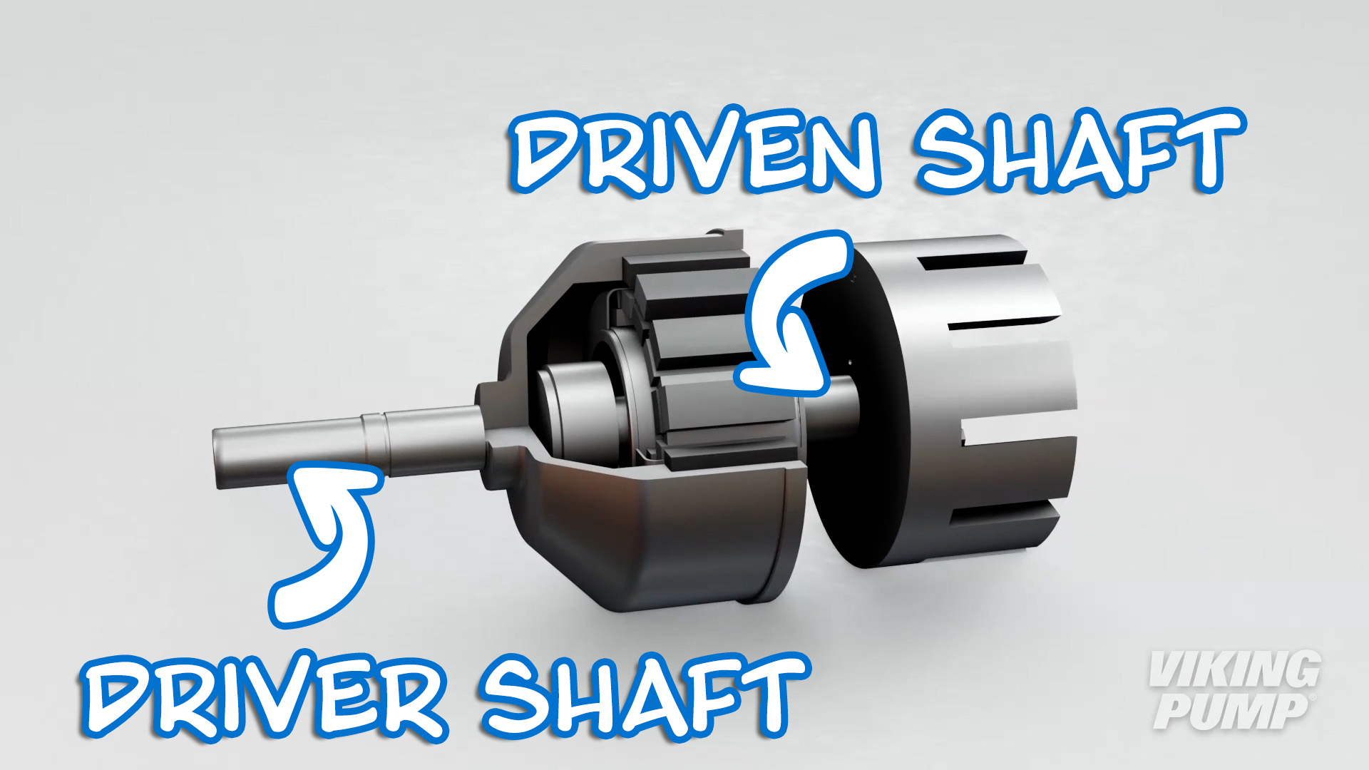
A sealless mag drive pump is comprised of two independent shafts. One shaft connects to the drive equipment (motor, reducer, etc.) and the second shaft connects to the pumping elements (rotor, gears, etc.). A magnetic coupling transmits the rotation of the drive shaft to the driven shaft inside the pump.
Sealless mag drive pumps can be any number of pump technologies including internal gear, external gear, vane, centrifugal and others.
Click here to view a video about how internal gear mag drive pumps work.
What are the disadvantages of pump packing?
Since a small amount of leakage is required to cool and lubricate packing, this seal type is a poor choice for thin, flammable, toxic, or other dangerous applications.
What are the advantages of pump packing?
Packing is cost-effective ideal for high temperature and thick liquids.
What is pump packing made out of?
Packing is one of the oldest forms of shaft sealing. Original packing was made of materials such as leather or rope. Today, packing materials typically include PTFE or compressed graphite.
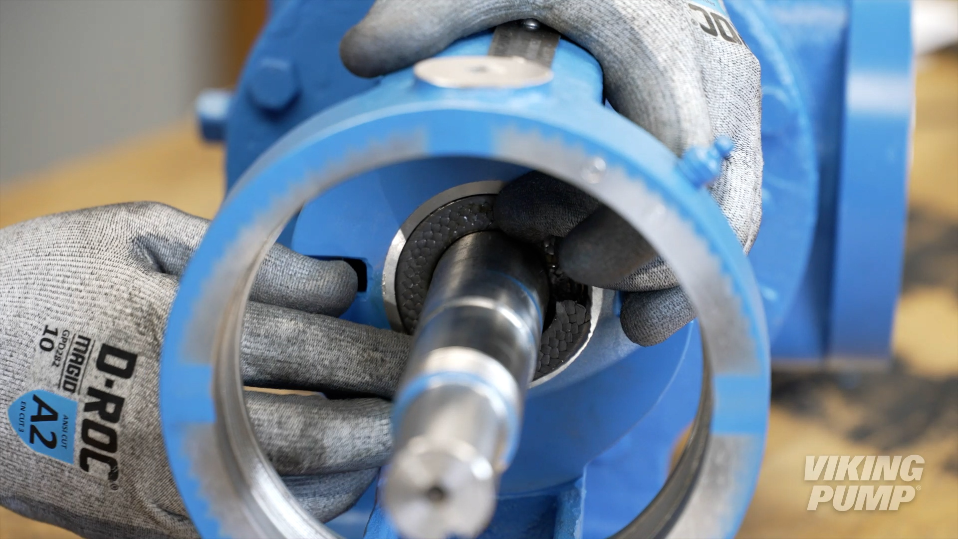
What is pump packing?
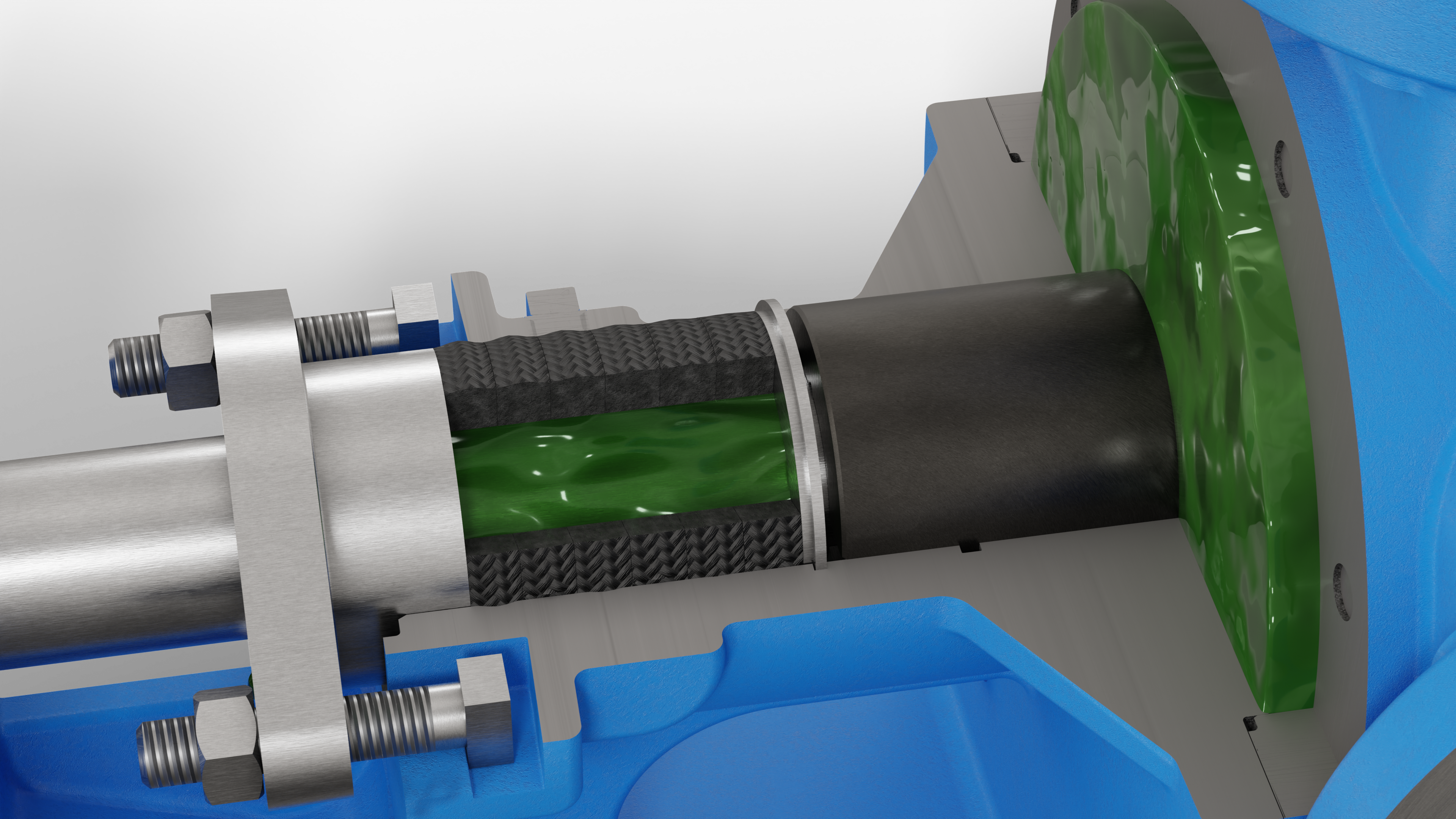
Packing is one of the most common and simplest seals for positive displacement pumps. Packing typically consists of braided or formed rings that are compressed in the stuffing box of a pump. As the packing is tightened, it squeezes up against the shaft and the stuffing box wall to create the seal.
|
|
 |
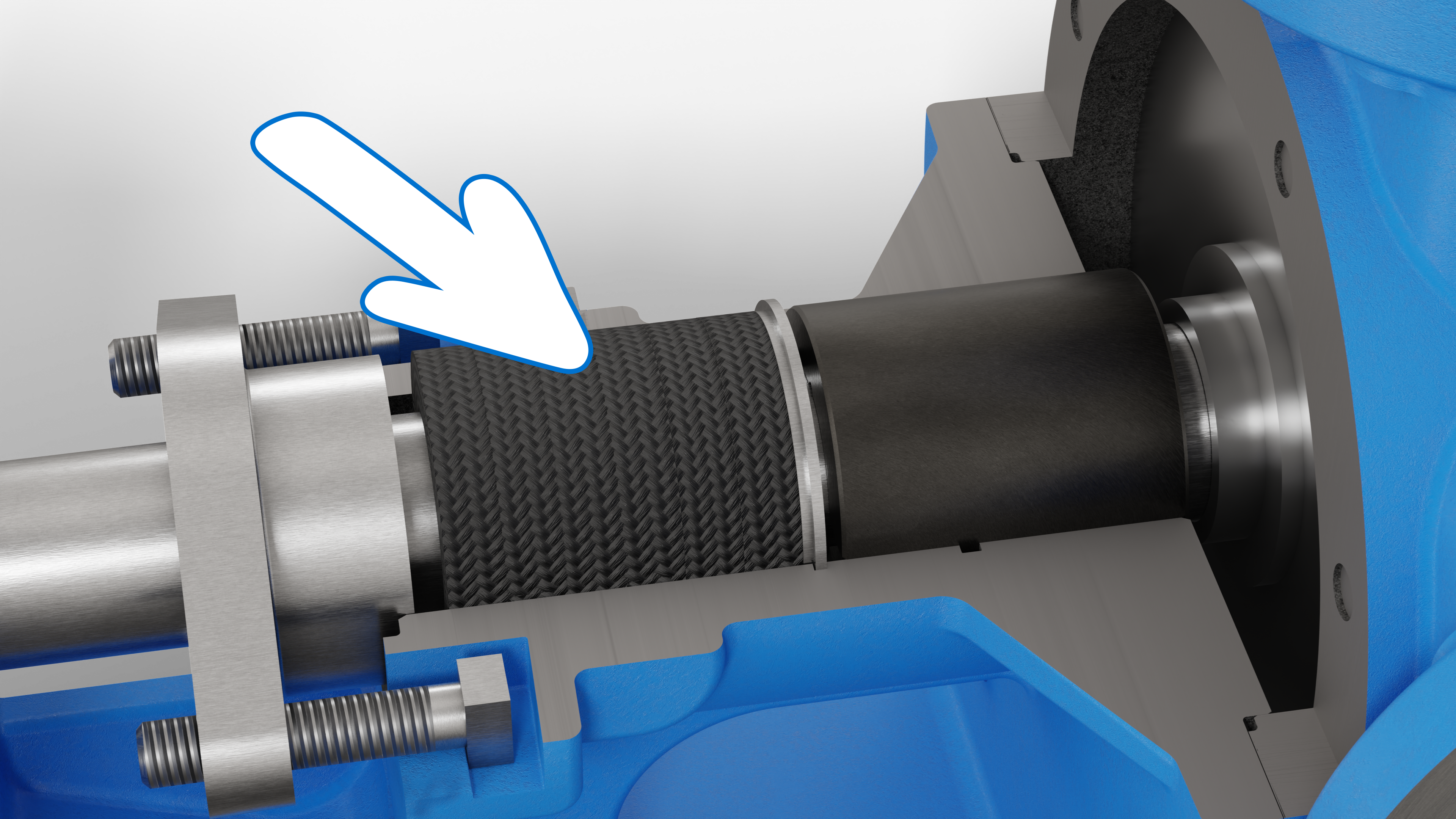
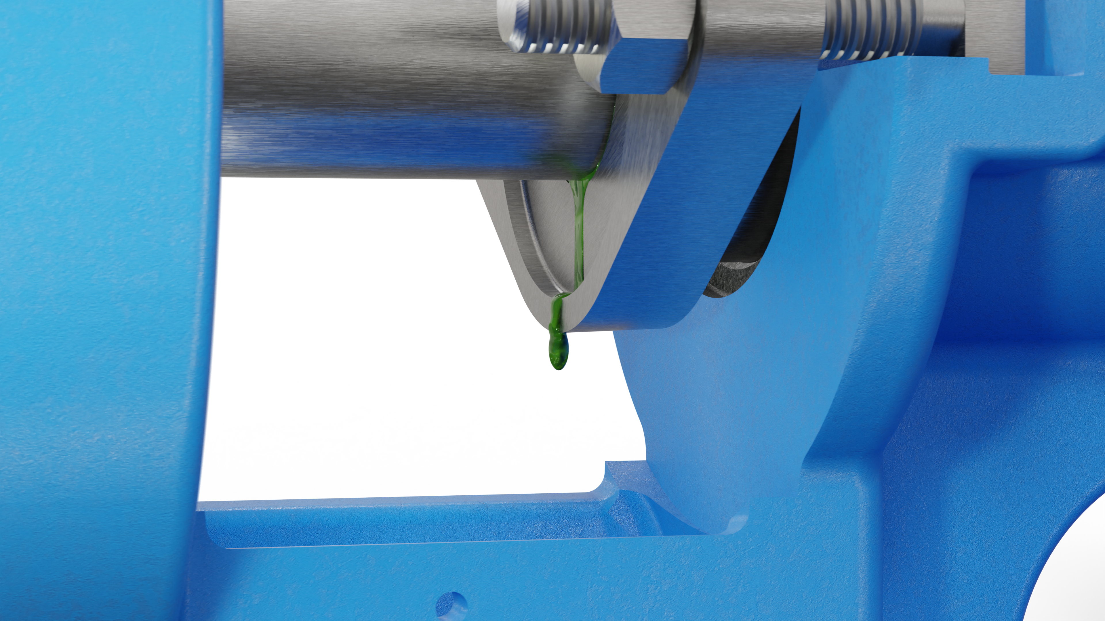
When the pump is operating, process liquid cools and lubricates the packing. The pump must leak or "weep" slightly to ensure proper lubrication.
|
|
 |
What is a dynamic o-ring seal?
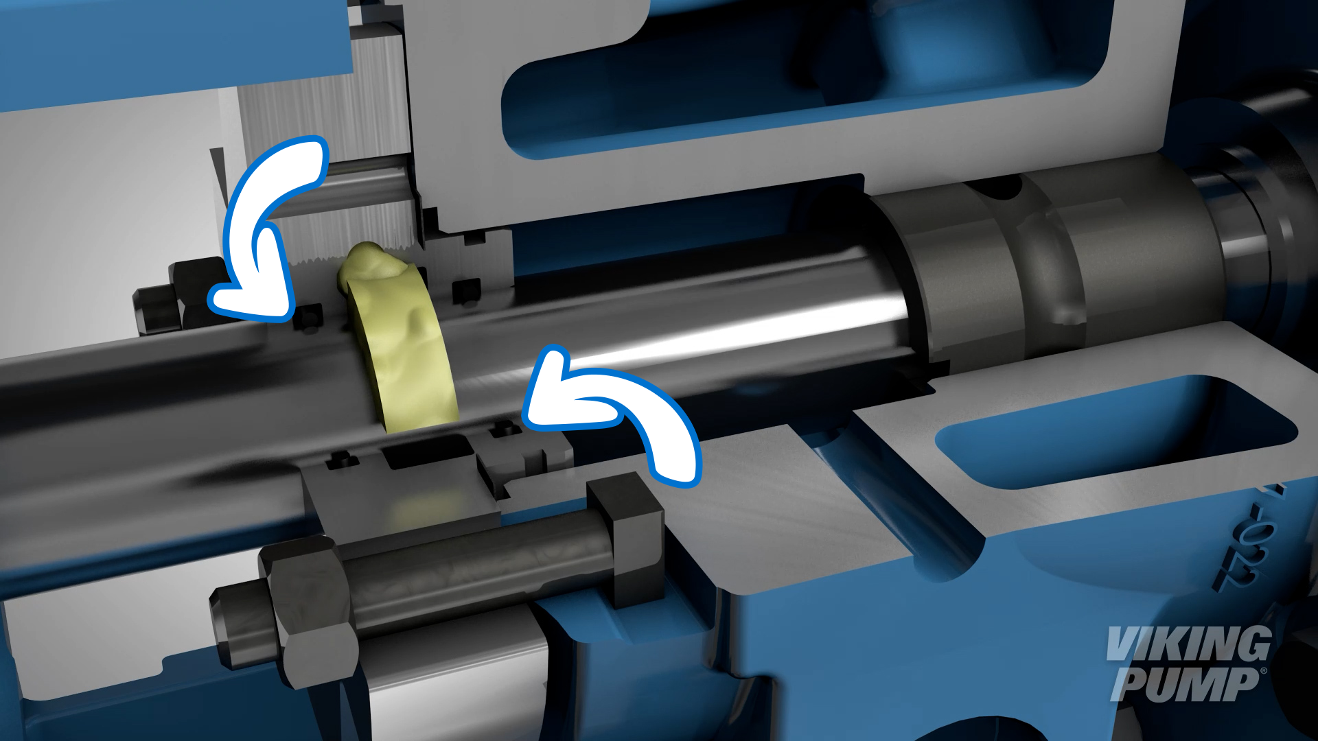
Dynamic o-ring seals are created between the rotating shaft and a stationary housing.
What is a static o-ring seal?
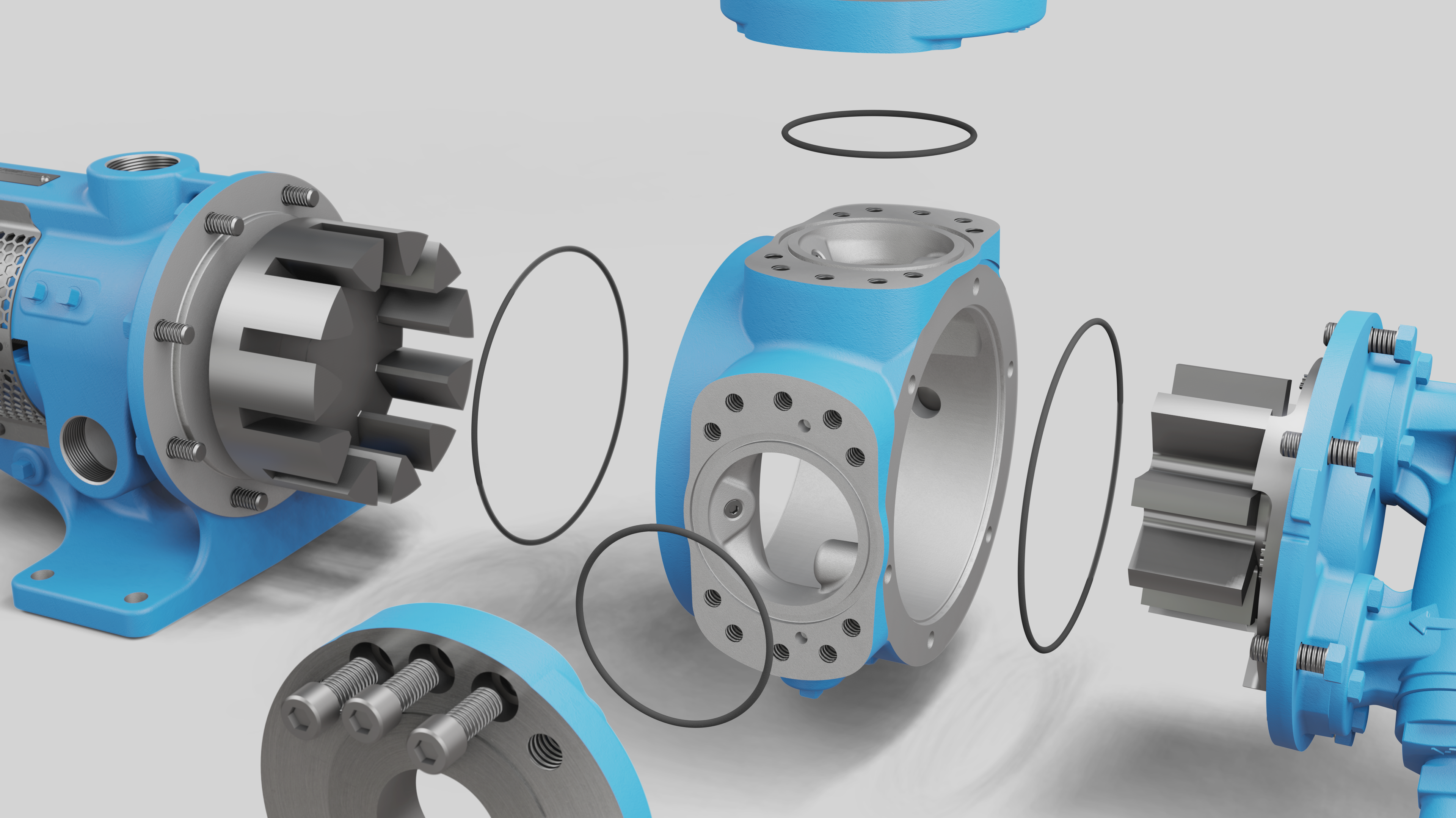
O-ring seals that are static are between pump parts where there is no relative motion. This can be between head and casing, casing and bracket, and casing and port connections.
What is an o-ring seal?
O-ring seals are any seal that consists of one or more elastomeric o-rings. These may be static seals wherein there is no relative motion between parts (i.e. an o-ring seal between a pump casing and bracket) or dynamic seals wherein the seal is created between a moving shaft and a stationary housing (i.e. O-Pro® shaft seals).
Different types of O-Pro® seals
There are currently three variations of the O-Pro® seal – the barrier, cartridge, and guard.
O-Pro® Barrier Seal
Viking Pump's O-Pro® Barrier seal is designed to replace packing and create a robust seal helps minimize pump leakage.
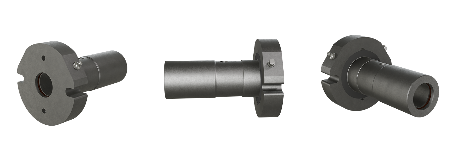
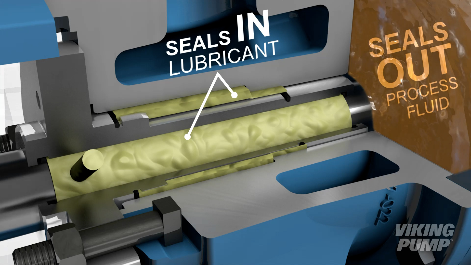
The O-Pro® Barrier seal, when installed, replaces the traditional bracket bushing and utilizes two sets of standard FKM o-rings (these can be exchanged based on customer needs) that create a sealing area between the seal and shaft and keep process fluid out of the bracket.
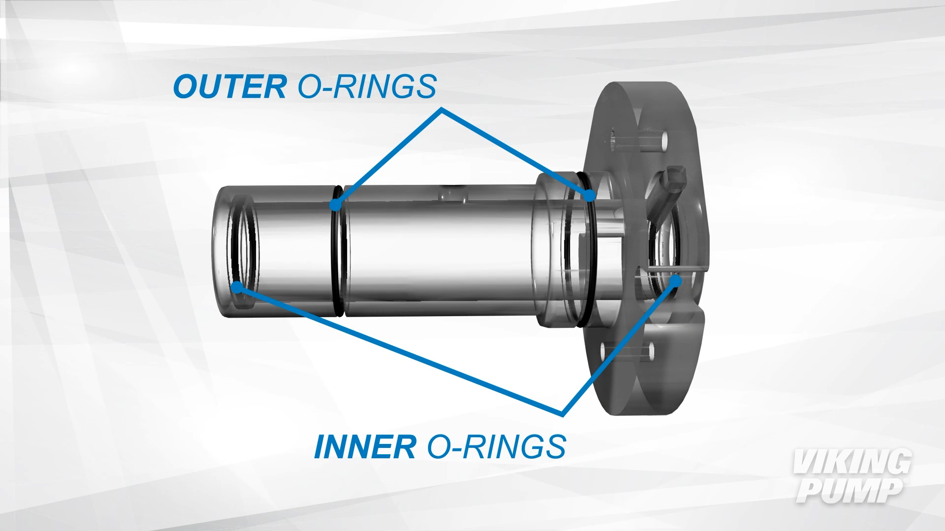
Application specific grease is injected into the bracket and fills the space between the seal and shaft.
The O-Pro® Barrier seal is designed for a number of applications like chocolate, peanut butter, molasses, wax, grease, starch adhesive, oils and more.
In this video, learn how to install an O-Pro® Barrier seal: https://youtu.be/nz0fP5OkjeY
O-Pro® Cartridge Seal
Viking Pump's O-Pro® Cartridge seal is stainless-steel and designed to meet the needs of many difficult to seal processes.
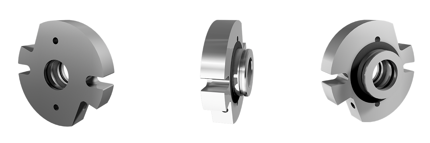
The O-Pro® Cartridge seal utilizes two internal FKM (or FFKM for high temperature or corrosive applications) o-rings and one flat gasket to create a sealing area between the seal and shaft - as well as a keep process liquid from leaking out of the bracket.
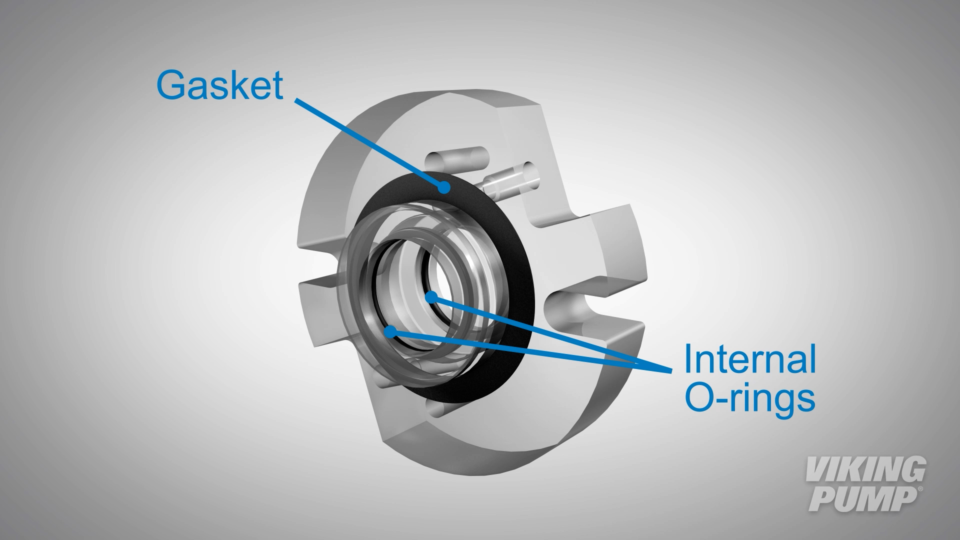
Application appropriate grease is injected into the grease fitting and fills the space between the two internal o-rings to lubricate the seal and shaft.
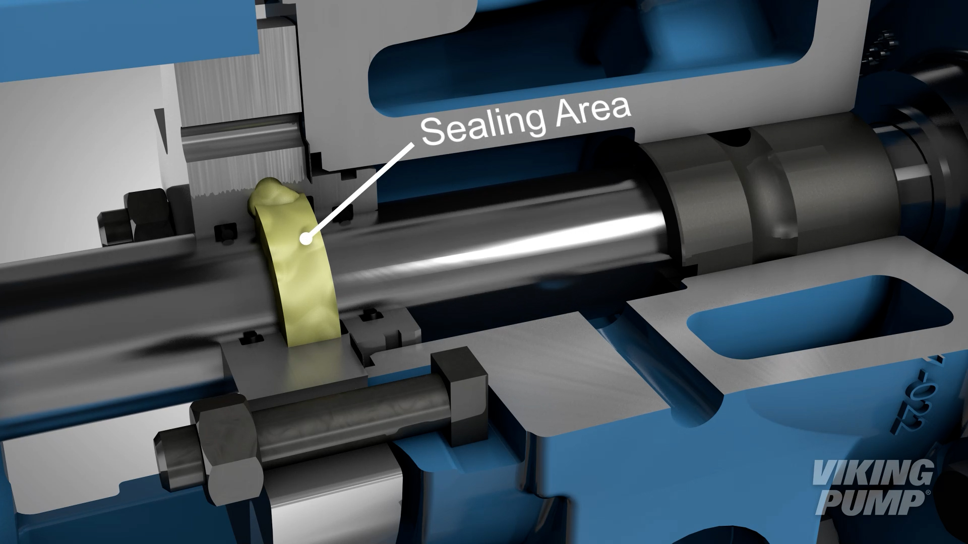
The O-Pro® Cartridge seal is designed for a number of applications including corn syrup, edible oils, paint, ink, grease, resin and more. With it's stainless steel construction, it meets the needs of many stainless steel processes.
In this video, learn how to install an O-Pro® Cartridge seal: https://youtu.be/ts8CNhWxu4s
O-Pro® Guard Seal
Viking Pump's O-Pro® Guard seal is stainless-steel and designed to meet the needs of many difficult to seal processes and extend the life of the pump.
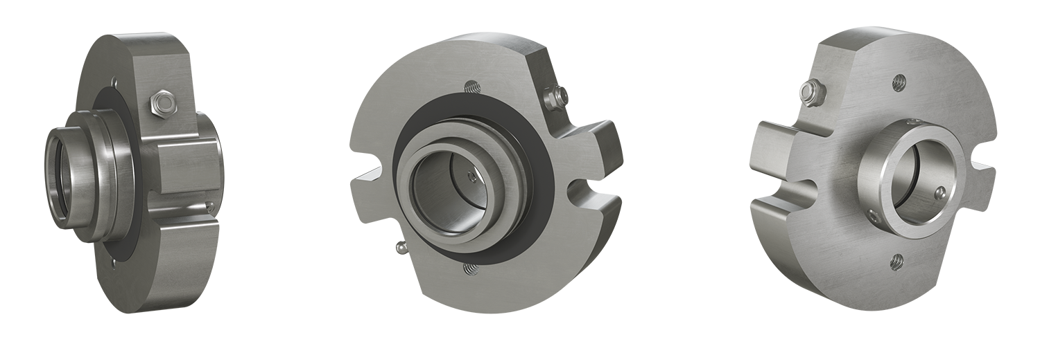
The O-Pro® Guard seal utilizes two sets of internal FKM o-rings (or FFKM for high temperature or corrosive applications). One pair is on the inside of a protective sleeve that is set to the shaft and another pair on the inside of the seal gland itself creating a sealing area between the seal and shaft - as well as a keeping process liquid from leaking out of the bracket. One flat gasket is used between the seal gland and bracket.
The protective sleeve prevents wear to the shaft that may be caused by o-rings that are in direct contact with the shaft.
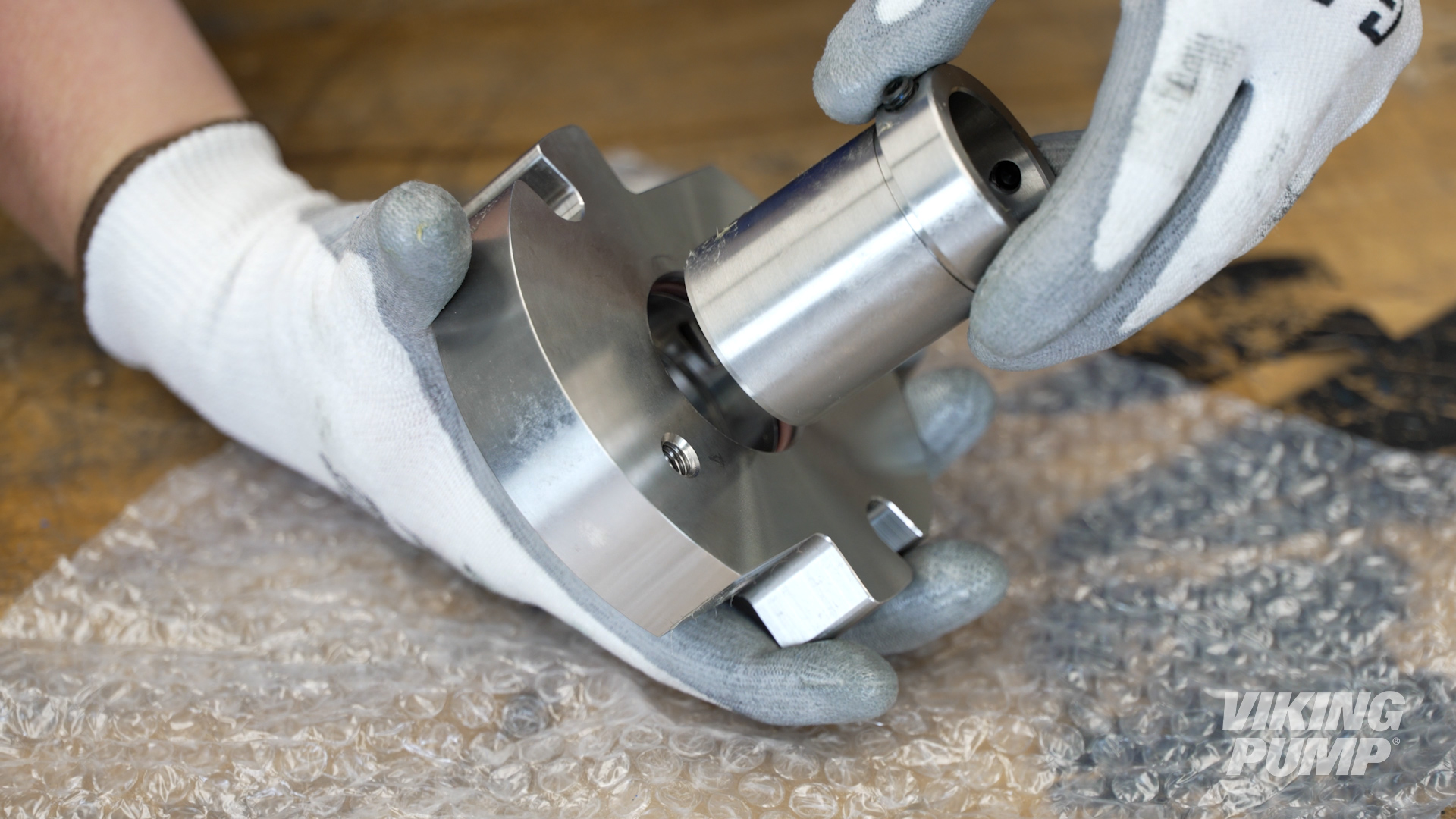
Application appropriate grease is injected into the grease fitting and fills the space between the two internal o-rings to lubricate the seal sleeve and gland.
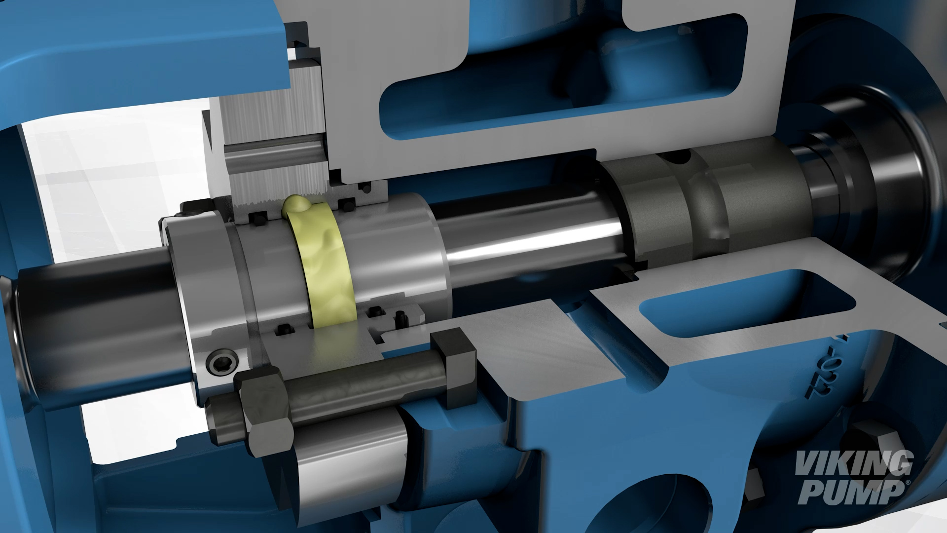
The O-Pro® Guard seal is designed for a number of applications including corn syrup, edible oils, paint, ink, grease, and more. With it's stainless steel construction, it meets the needs of many stainless steel processes.
In this video, learn how to install an O-Pro® Guard seal: https://youtu.be/FI8pdh4bcFE
What is an O-Pro® seal?
O-Pro® seal technology is Viking Pump’s line of patented seals which utilize a series of o-rings to create a robust seal and lubrication chamber, all in one housing.
What are the different types of mechanical seals?
There are many different seal types and designs when it comes to mechanical seals. Here are a few common examples for those used in Viking pumps:
- Single component seal – made up of a static and rotary seal face and pushed together by a spring. Primary seal is created by a film of process liquid between the two seal faces. Secondary seals are created by o-rings, bellows, or gaskets.
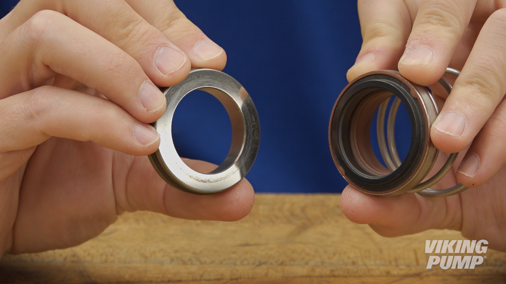
- Cartridge mechanical seal – all of the working parts of the come in a pre-set housing. This makes installation significantly easier.
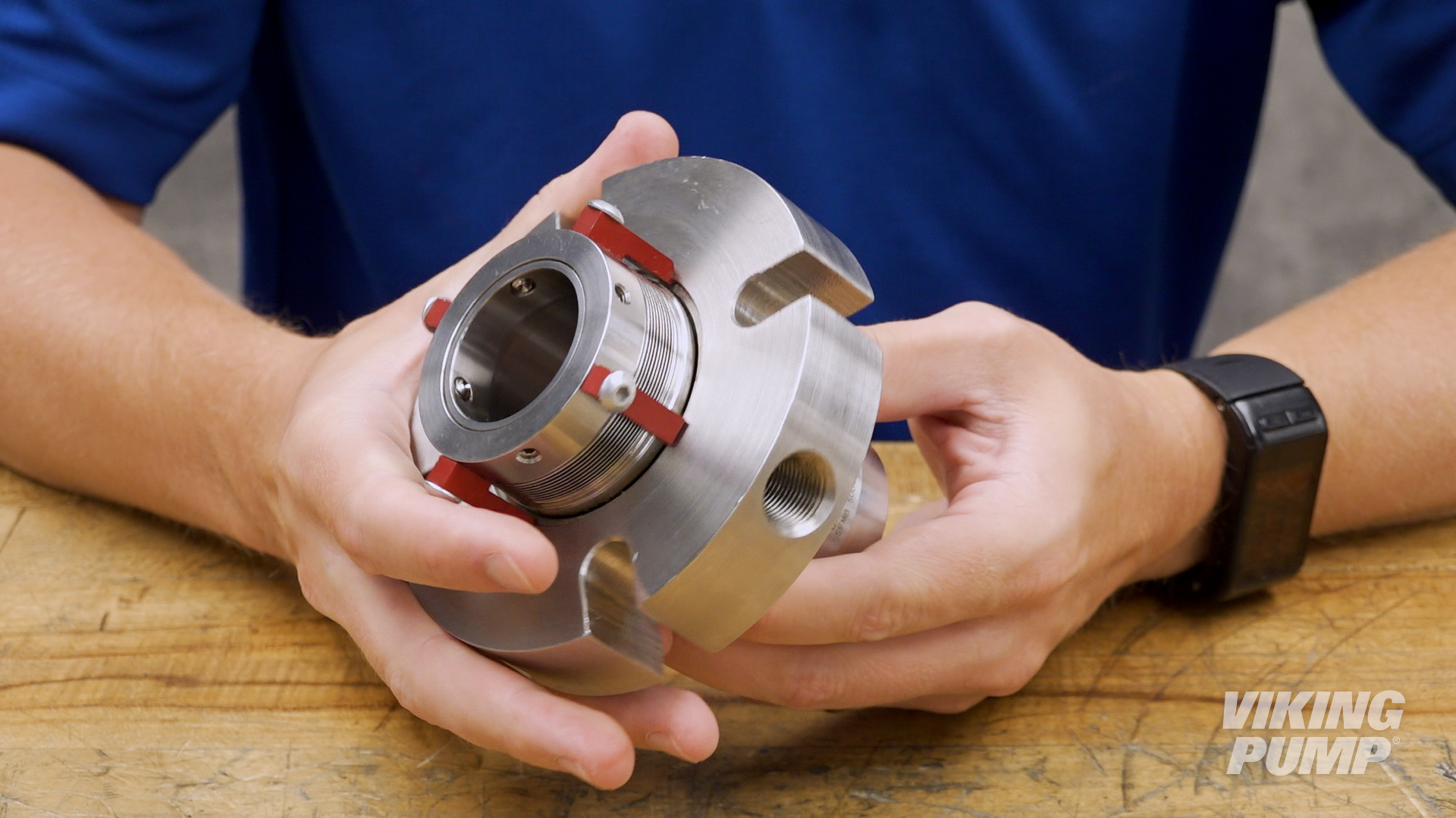
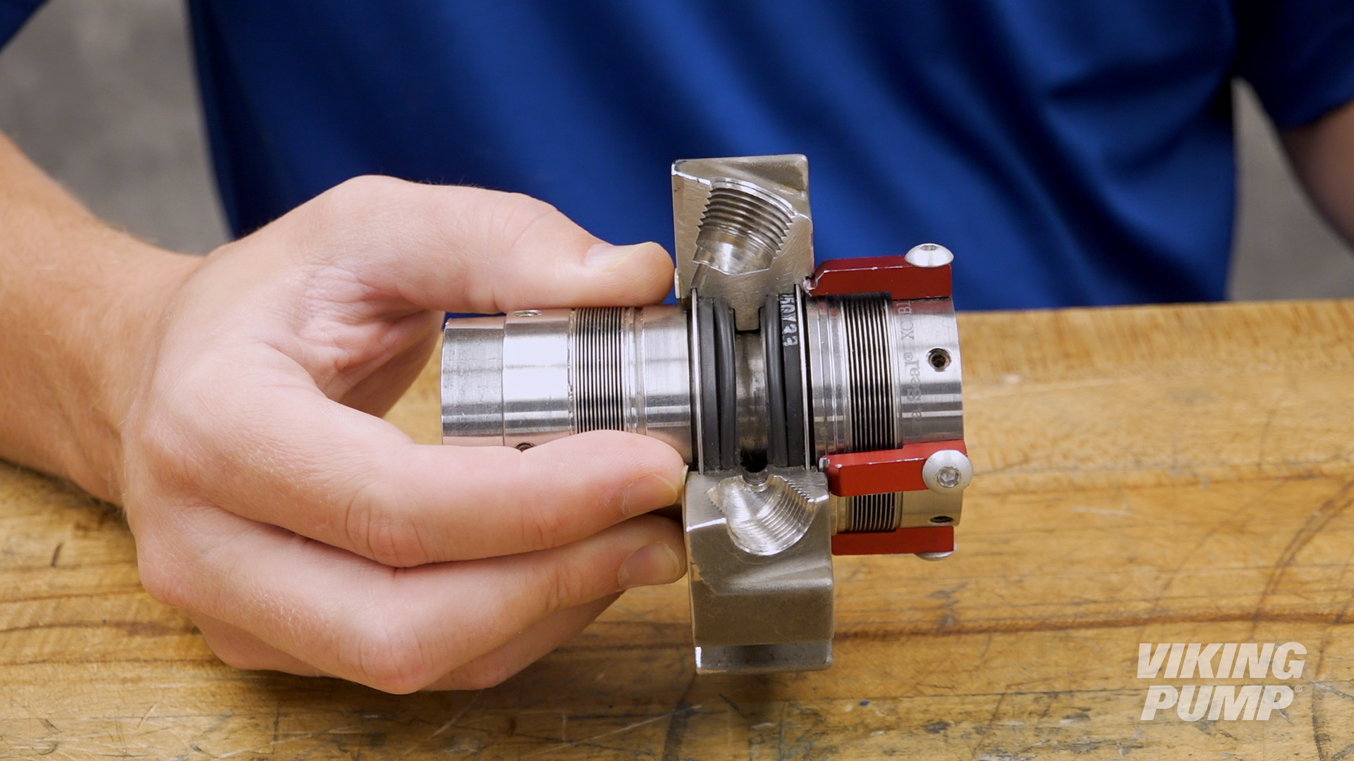
- Double Mechanical seals – These seals utilize two mechanical seals in a housing. A barrier liquid is applied into the housing between the two seals. This prevents exposure of the process liquid to the environment and it used for toxic, flammable, or difficult to seal liquids.
How does a mechanical seal work?
Mechanical seals work by utilizing two separate seal faces. One seal face (static) is typically installed into the pump housing, or bracket, while the other (rotary face) is installed onto the pump shaft. These two seal faces are glossy and highly finished. When liquid is being pumped, process fluid will work it’s way toward the seal faces. When liquid finally enters the space between the seal faces, a hydrodynamic film is created which creates the seal and lubricates the faces. This is the primary seal. A spring helps hold the seal faces together to maintain the primary seal.
Secondary seals are created by o-rings, bellows, or gaskets that prevent leakage past the gland or along the shaft.
What is a mechanical seal?
Mechanical seals prevent liquid leakage by creating a hydrodynamic liquid film between two highly finished surfaces. In pumps, the simplest mechanical seals have one rotating surface and one static surface. They come in a variety of types and can be found in different pump technologies e.g., internal gear, external gear, and centrifugal pumps.
How to install a lip seal
Here are some basic steps for installing a lip seal. These steps will vary depending on the type of seal and the pump technology it’s going into, but for this example these steps relate to installing a lip seal into Viking Pump’s G and GG sized 75 Series™ pumps.
Note: Before any work begins on a pump, please consult the appropriate technical service manual for safety information. A copy of the latest revision can be found on our website.
What you need for installation
To install the two lip seals into a G or GG sized 75 Series™ pump, you’ll need two pieces of equipment:
- Arbor Press
- 2 ¾” press fixture
Pressing in the sealsThe 75 Series™ has two lip seals that are pressed in one at a time. The lips face outward from each other when installed. For G and GG sized pumps, the lip seals will be pressed in from the flange side of the pump. |
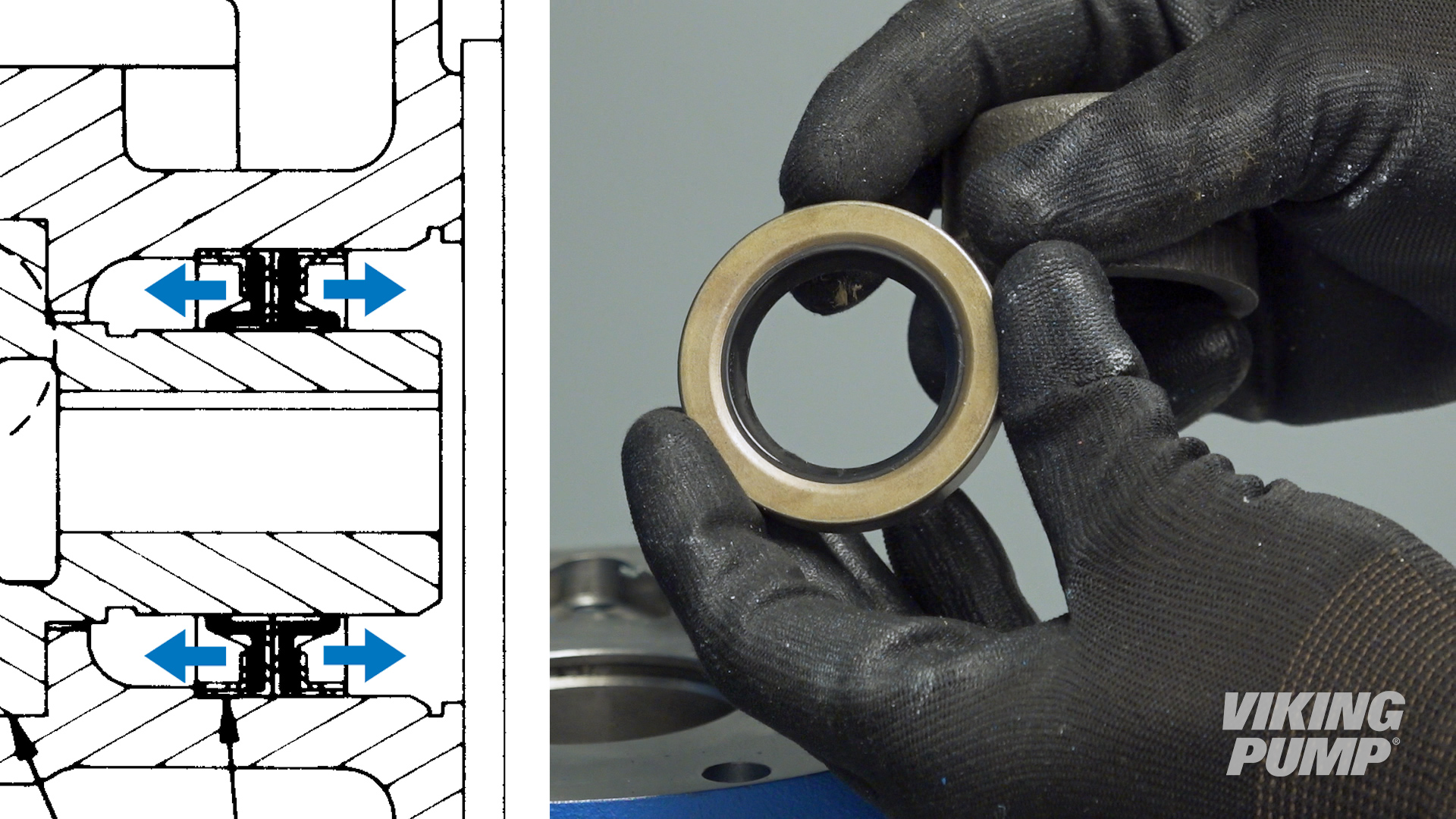 |
| Place the first lip seal into the bore with the lip down. | 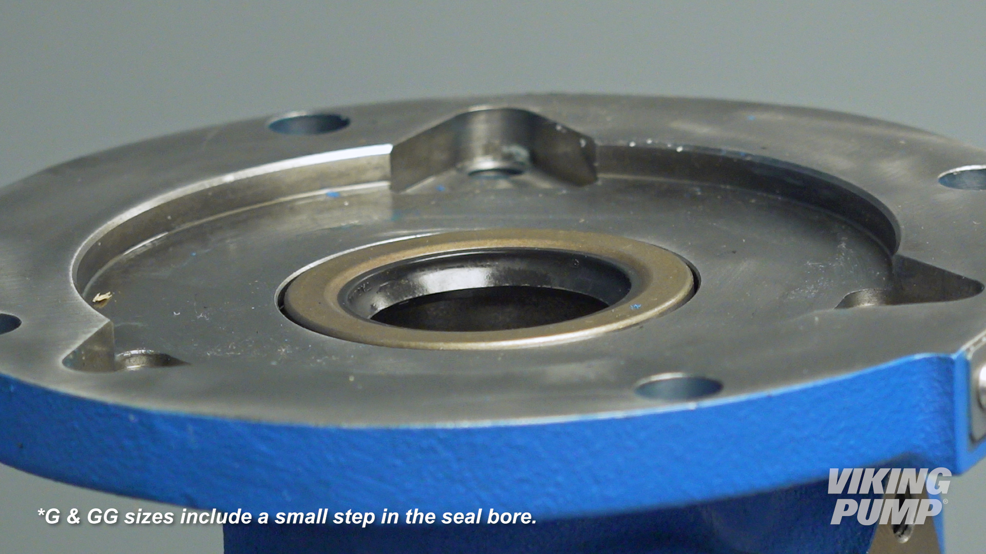 |
| Press until it stops at the bottom of the seal bore. |
|
| Place the second lip seal with the lip facing up and press until it stops against the first lip seal. |
|
| Pack the area between the lips with compatible grease. | 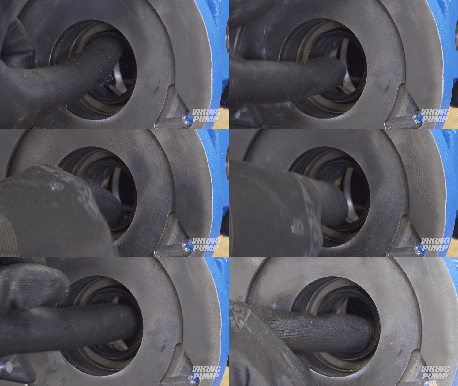 |
| You can now complete the rest of the pump assembly. | |
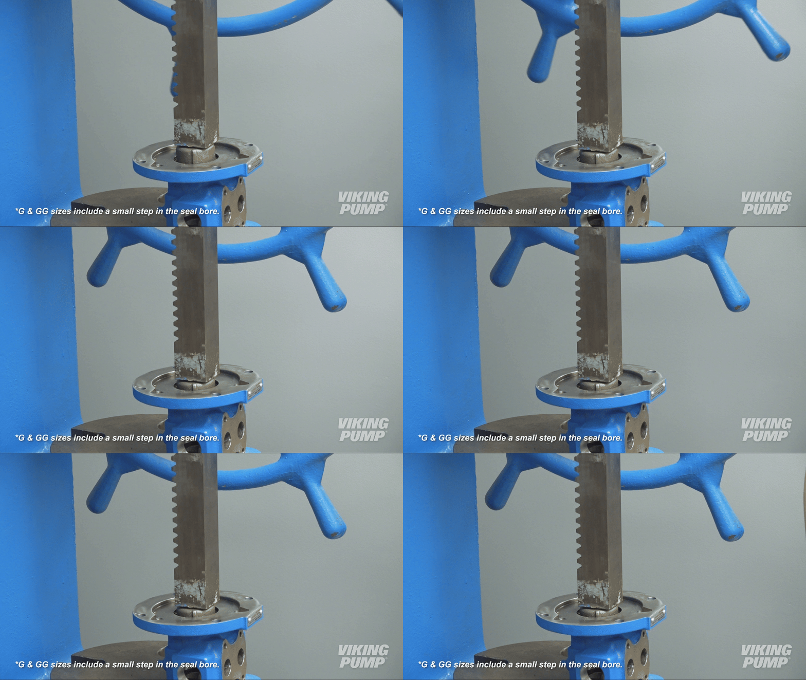
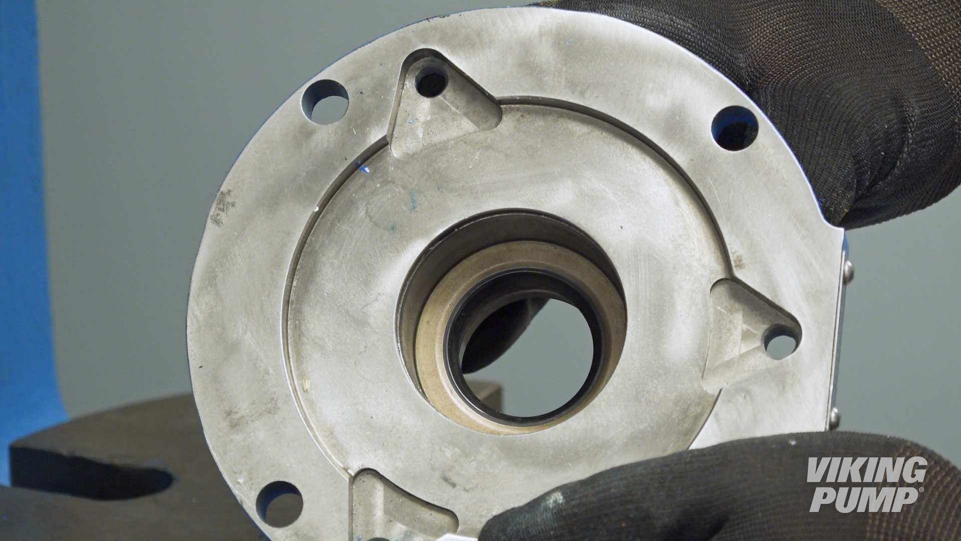
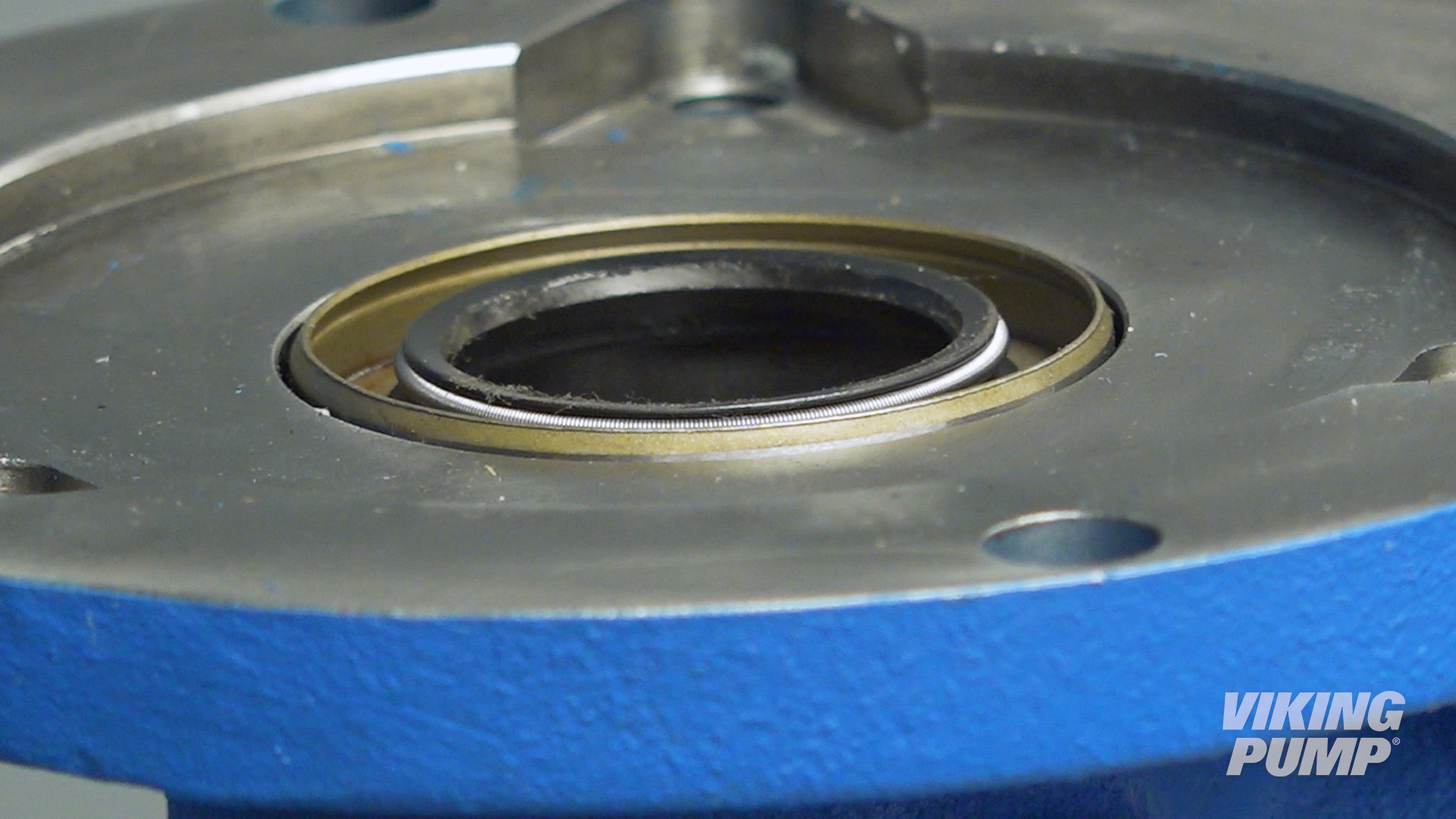
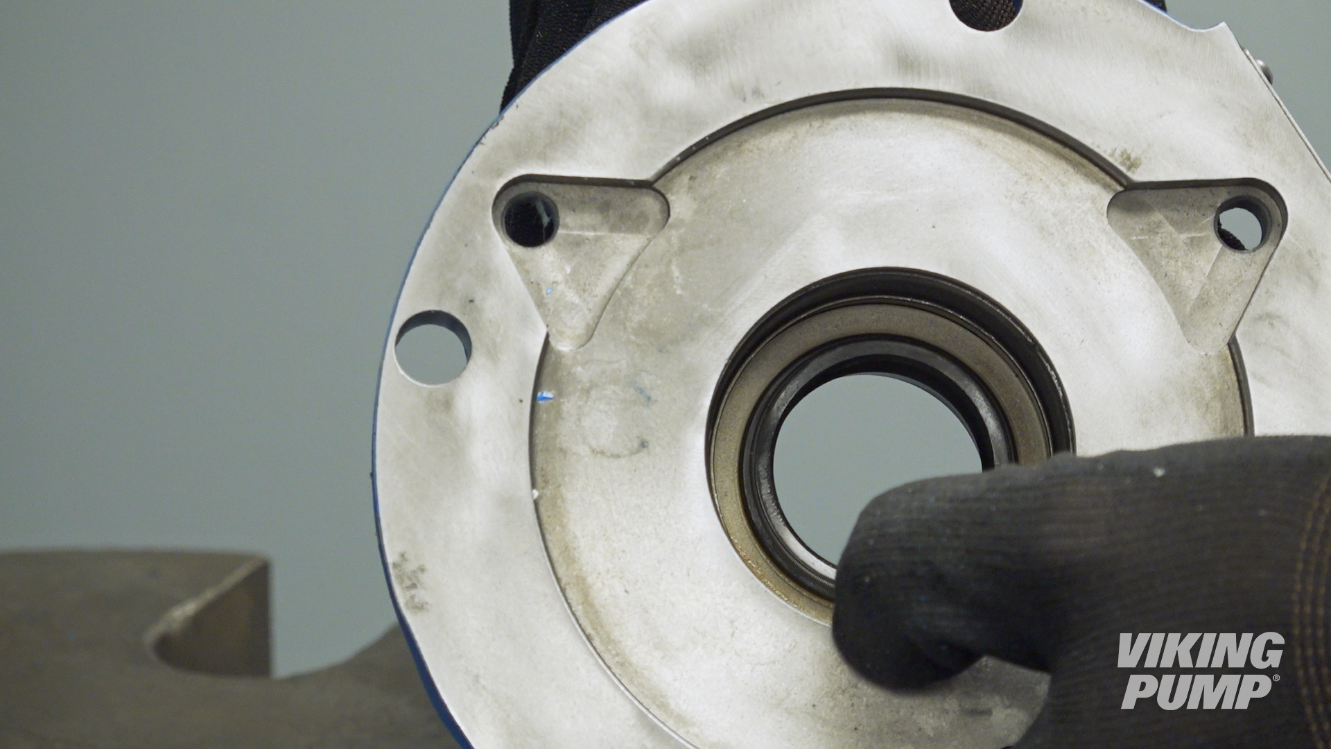
What are the limitations of lip seals?
Lip seals are not ideal for abrasive applications and they have modest inlet pressure limits when compared to other seal technologies.
What are the benefits of using a lip seal in a pump?
Lip seals are a simple, economical, and compact seal solution. Their narrow profile makes them easy to fit into small pumps and tight spaces.
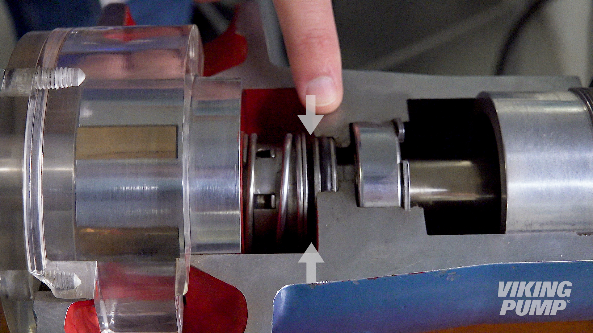
What is a lip seal?
Lip seals consist of a flexible elastomeric lip inside a rigid housing.
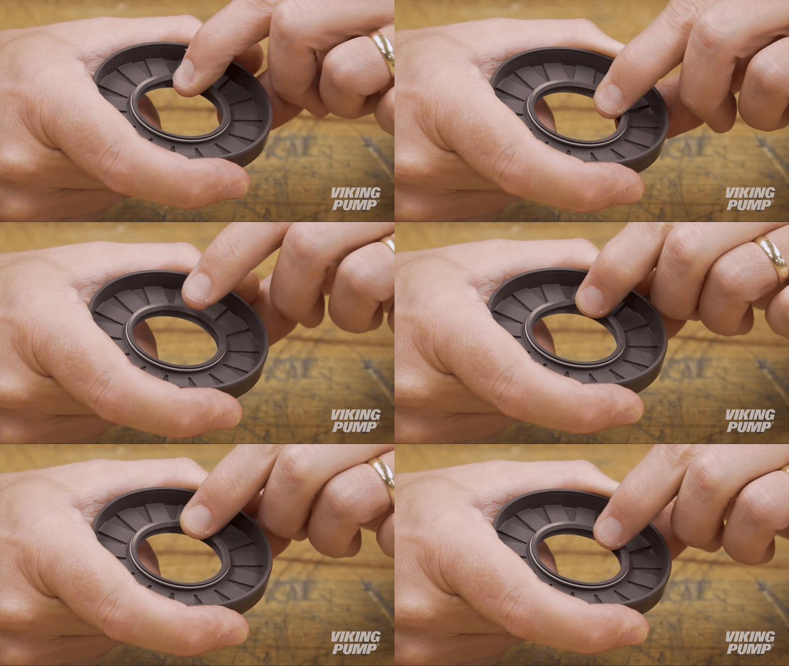
The lip seal is stationary and the shaft rotates inside.
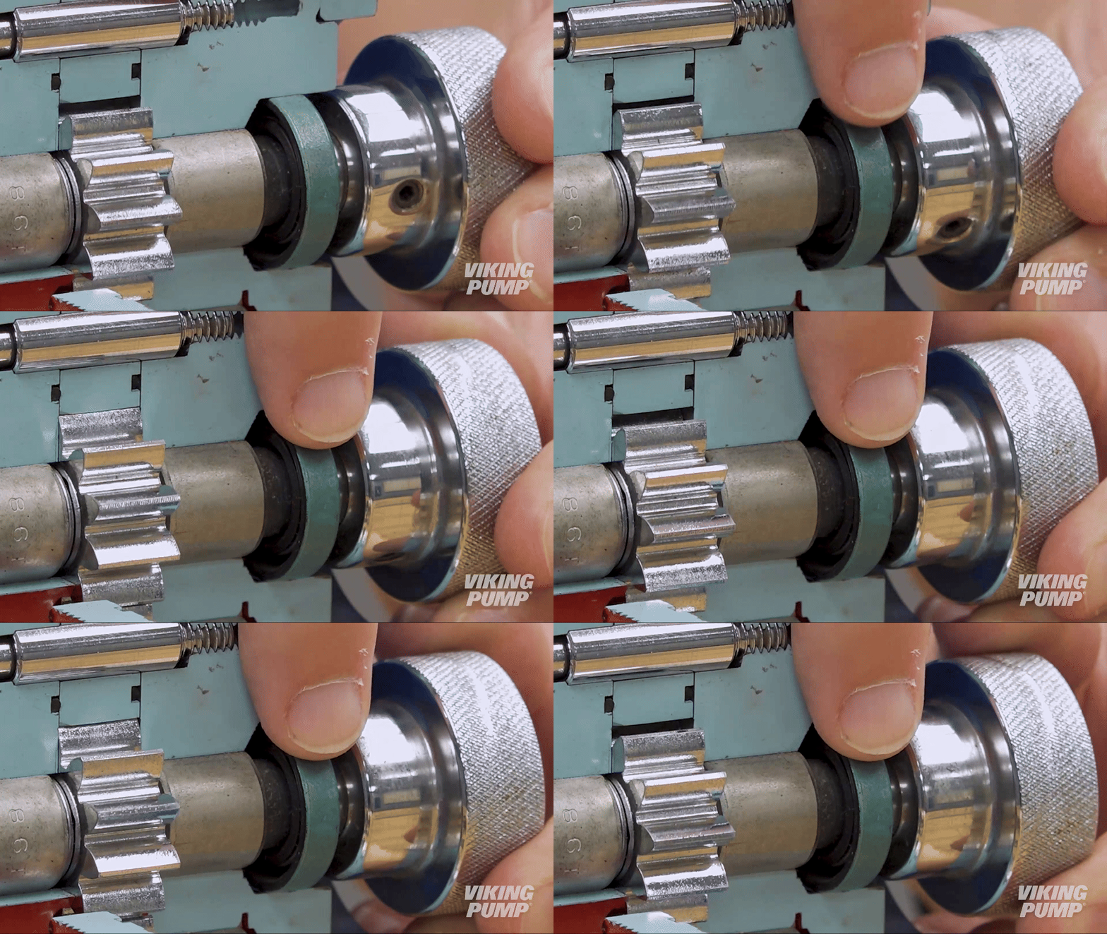
An inboard spring helps to energize the lip and keep it in contact with the shaft while an outboard lip, called a wiper, prevents the ingress of contaminants from the outside environment.
Click here to view the Pump Report on this topic.
How does a component mechanical seal work?
Component mechanical seals work by utilizing two separate seal faces. One seal face (static) is typically installed into the pump housing, or bracket, while the other (rotary face) is installed onto the pump shaft. These two seal faces are glossy and highly finished. When liquid is being pumped, process fluid will work it’s way toward the seal faces. When liquid finally enters the space between the seal faces, a hydrodynamic film is created which creates the seal and lubricates the faces. This is the primary seal. A spring helps hold the seal faces together to maintain the primary seal.
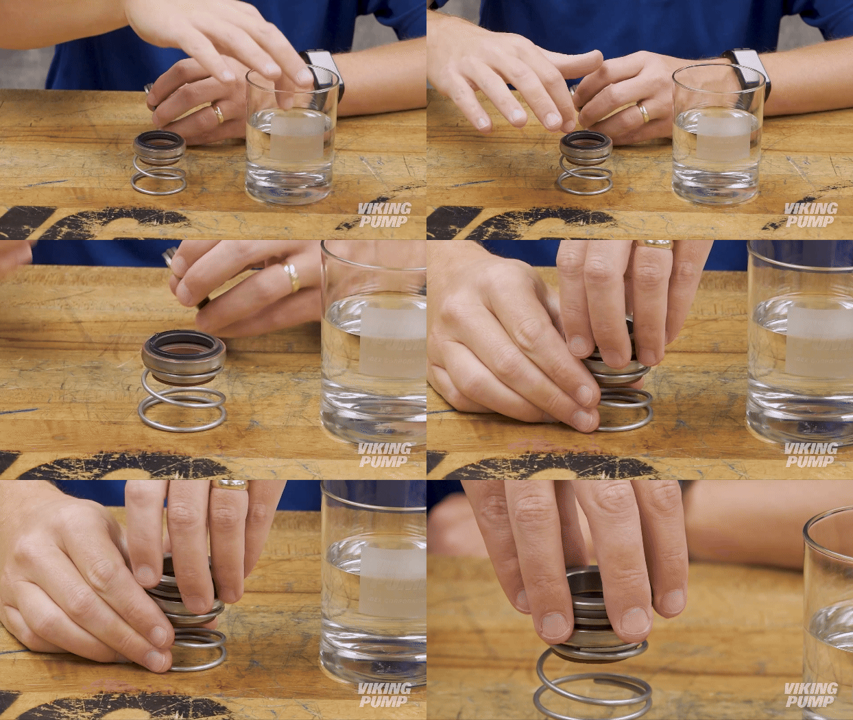
Secondary seals are created by o-rings, bellows, or gaskets that prevent leakage past the gland or along the shaft.
What is a component mechanical seal?
Component mechanical seals consist of two basic parts called faces. One face rotates with the shaft, while a second is held stationary in the pump housing. The primary seal is created between these two seal faces.
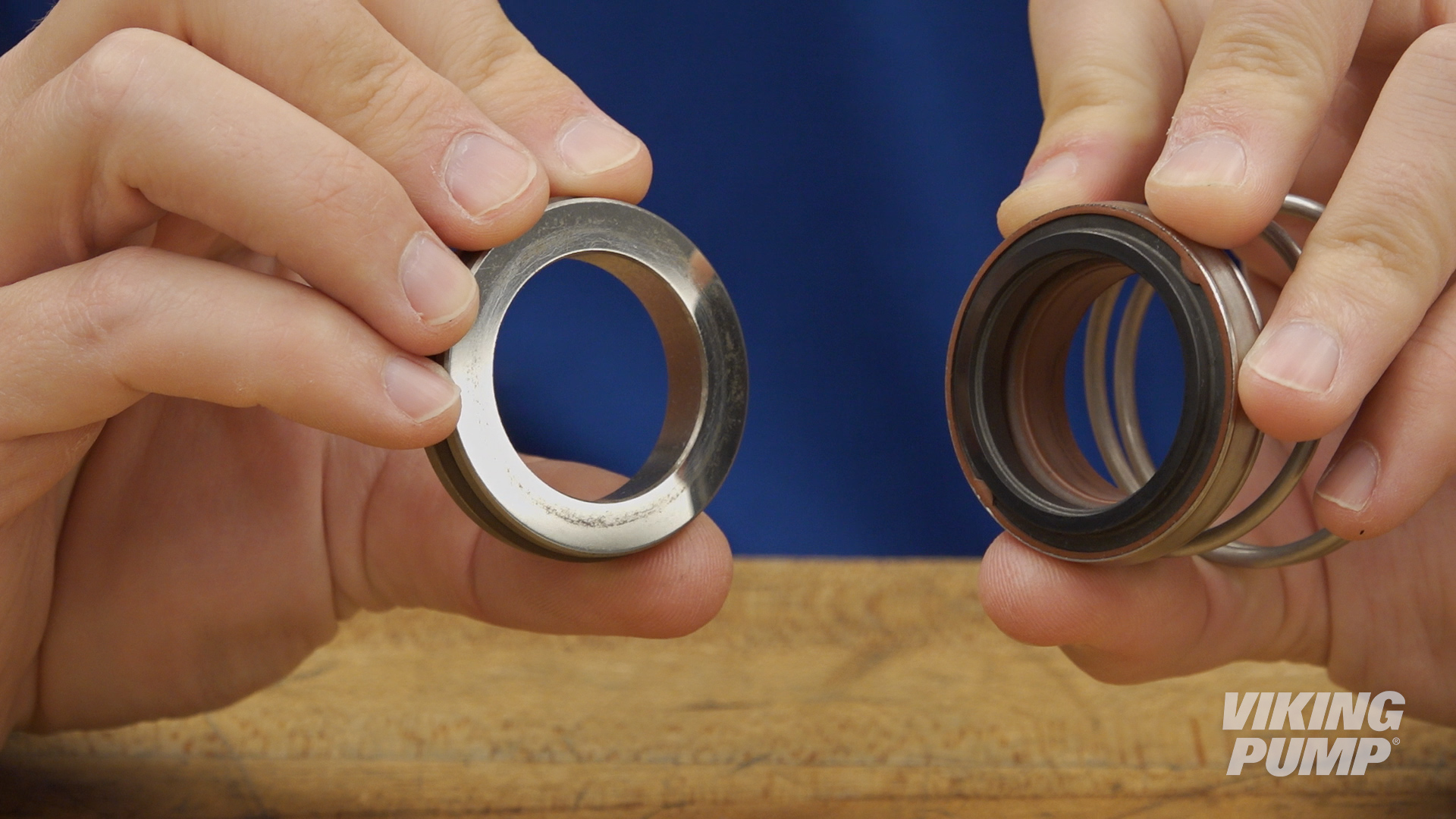
How do you install a behind the rotor seal?
Here are some basic steps for installing a behind the rotor seal. These steps will vary depending on the type of seal and the pump technology it’s going into, but for this example these steps relate to installing a single component PTFE behind the rotor seal into a stainless steel internal gear pump.
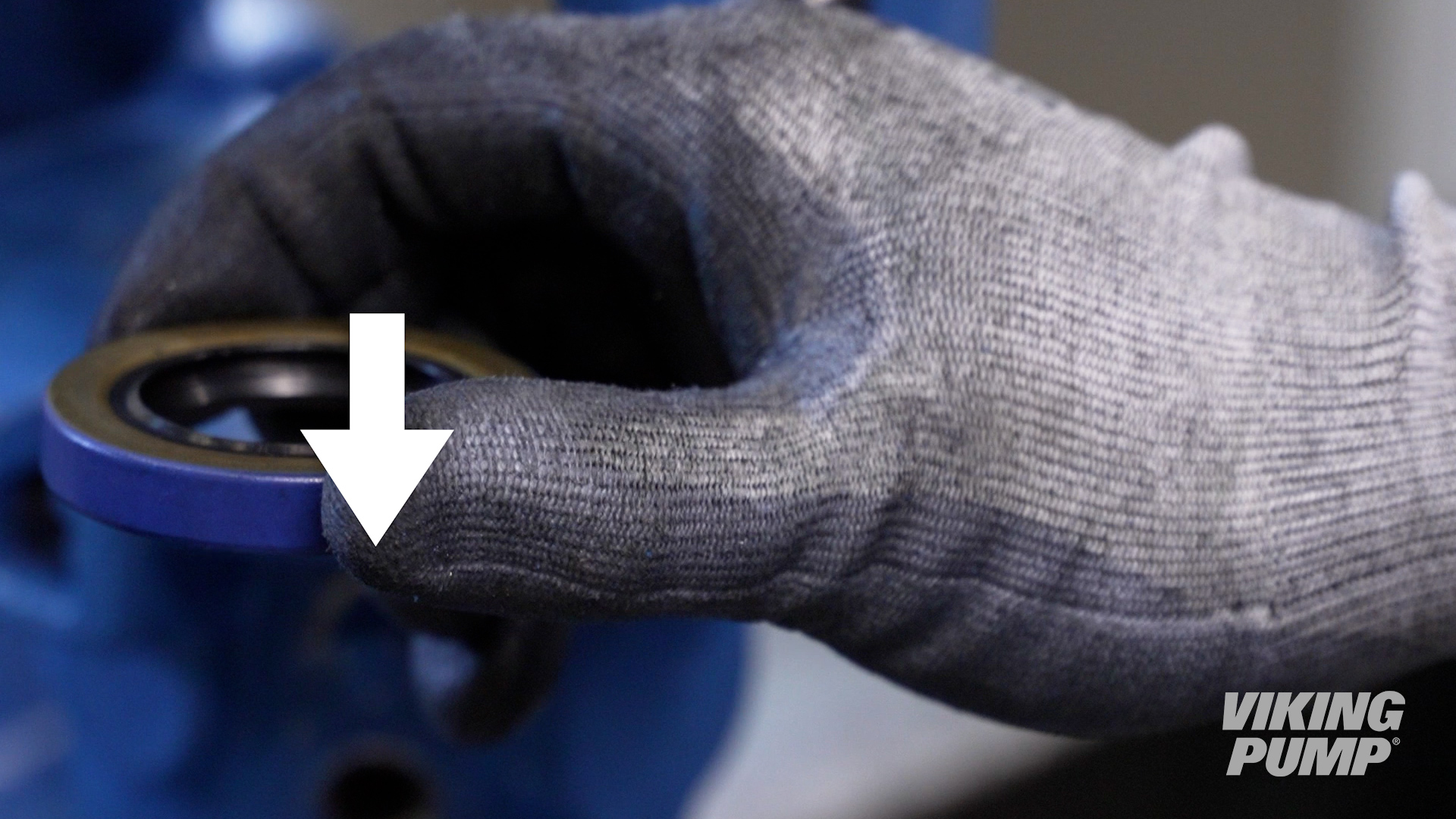
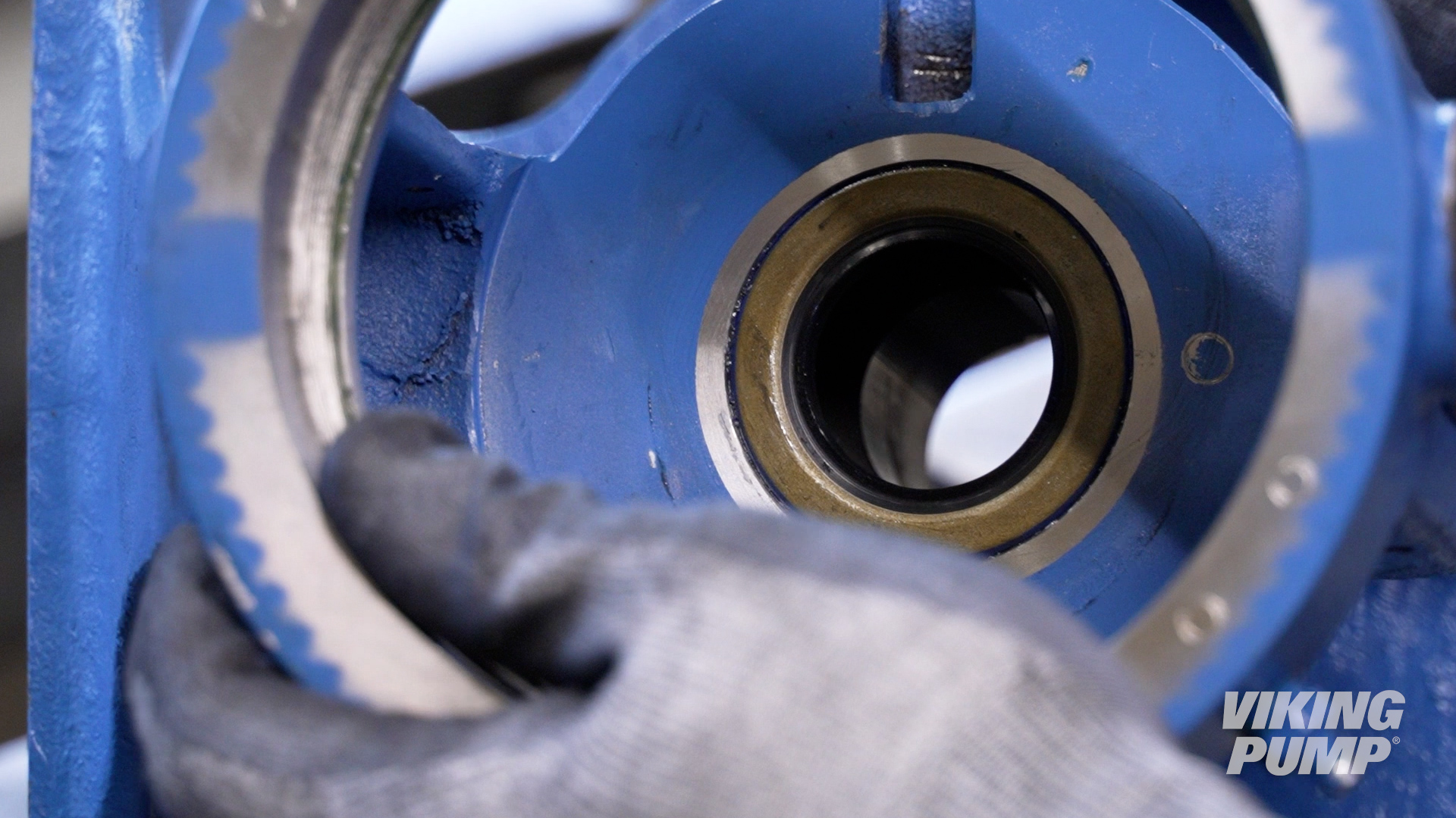
| 1. With the pump disassembled, first install the bracket lip seal by using an arbor or hydraulic press. Install with the spring side down until it is flush with the face of the bracket. |
|
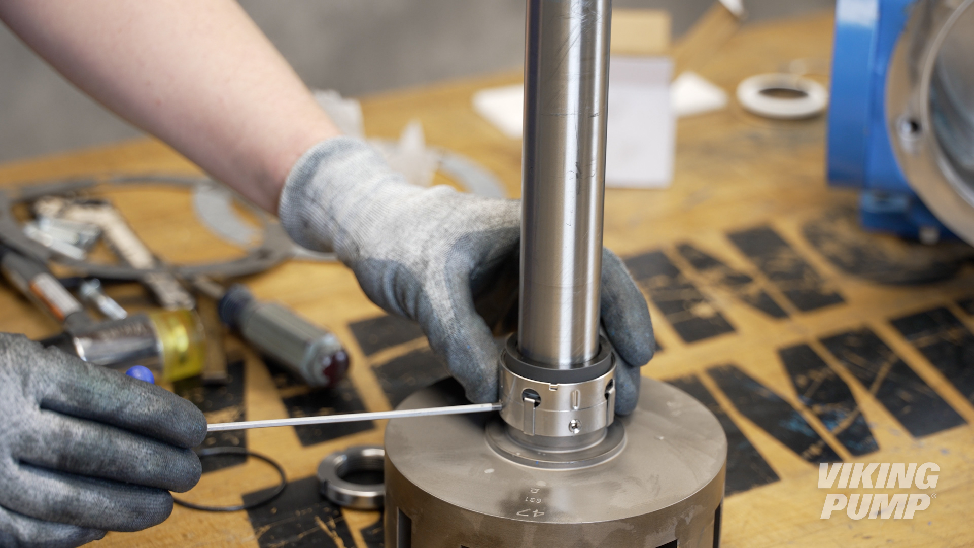
| 2. Install the provided installation sleeve onto the shaft. Make sure to lubricate the sleeve and shaft. Then install the seal rotary member until it makes contact with the back of the rotor. Then tighten the seal set screws evenly. |
|
| 3. Remove the seal clips to engage the seal. | 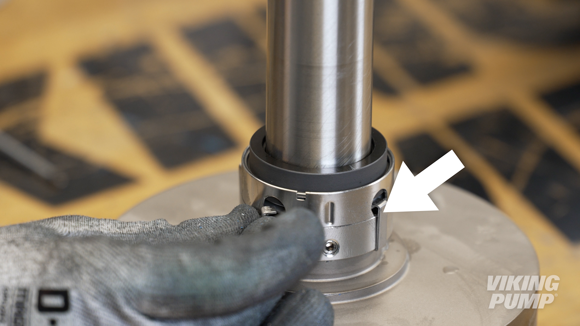 |
| 4. Next, with the pump oriented vertically with the bracket down, install the seal spacer ring. | 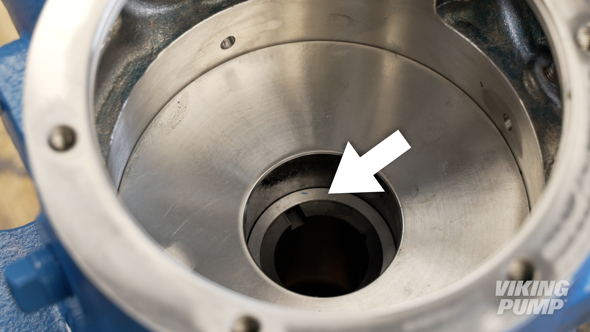 |
| 5. Install the seal seat with the pins down and aligned with the grooves in the bushing. Carefully push the seal until it is fully seated against the seal spacer. |
|
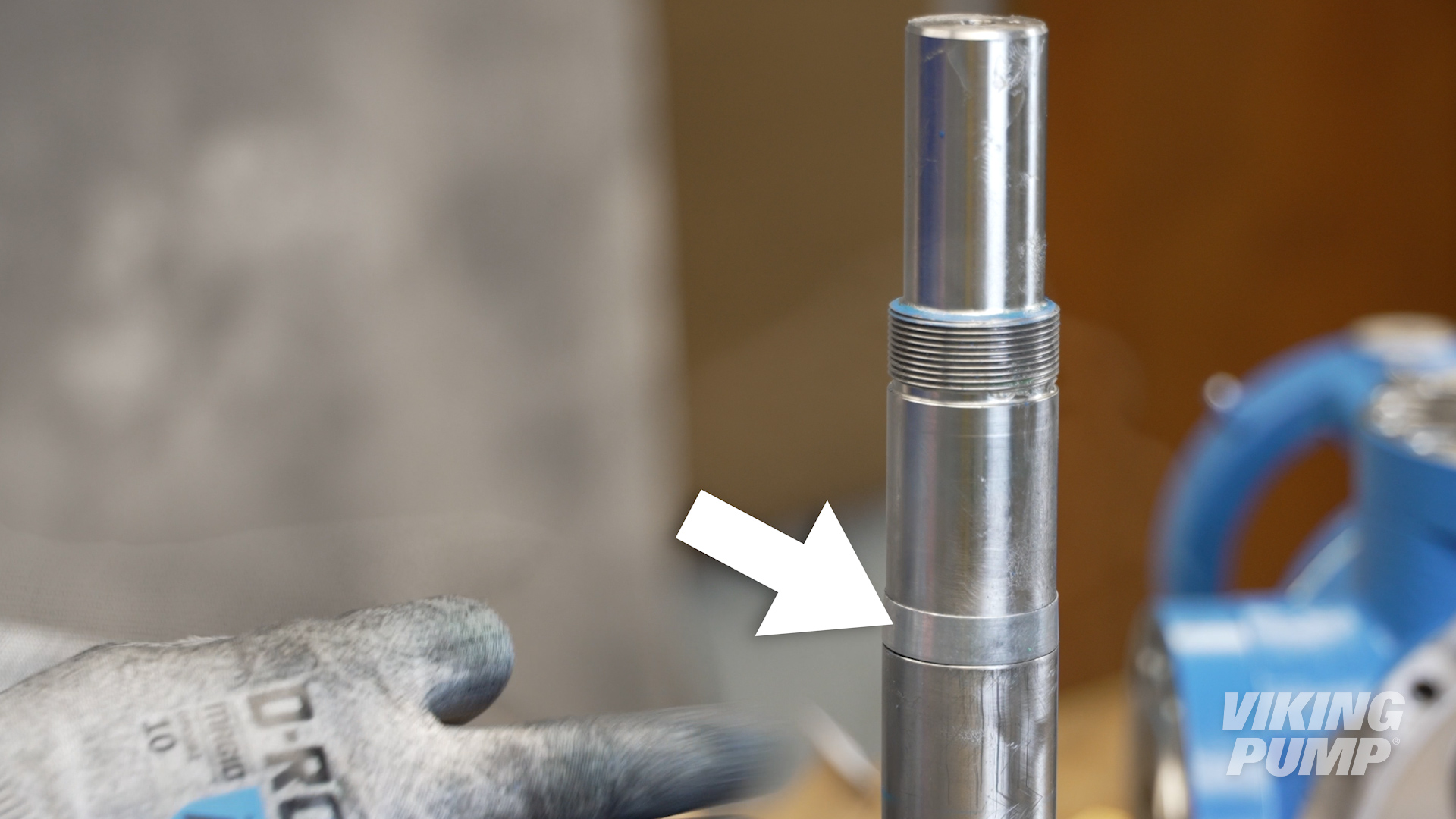
| 6. Tape the threads on the shaft before installing to prevent damage to the bracket lip seal. Lubricate then install. | 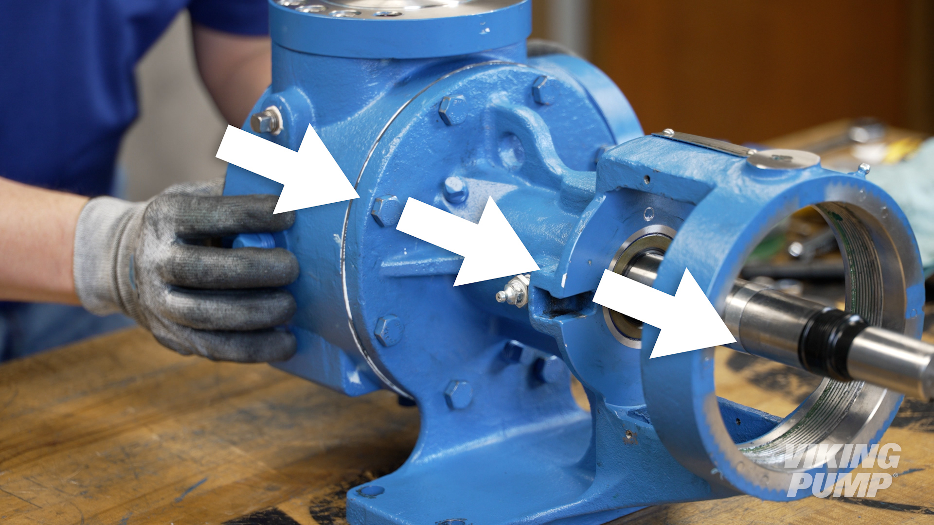 |
| 7. Remove the tape and seal installation sleeve. | |
| 8. At this point, the seal is engaged and pushing the rotor/shaft out of the pump, the bearing housing will need to be installed to aid with head installation. | |
| 9. Reinstall the half-round rings, bearing spacer collar, bearing housing, lock washer, and locknut. Fully tighten the locknut. | |
| 10. Loosen the bearing housing to open the clearance and pull the rotor into the casing. Use caution when turning the bearing housing and stop if you encounter resistance to avoid over-compressing the seal. | |
| 11. Install the head gasket and idler onto the pump, then install the head onto the casing. | |
| 12. Set the end clearance. | |
| 13. Finally, grease the bracket with application appropriate grease. Continue to pump in grease until grease begins to exit the relief fitting. Make sure to rotate the pump while greasing. | 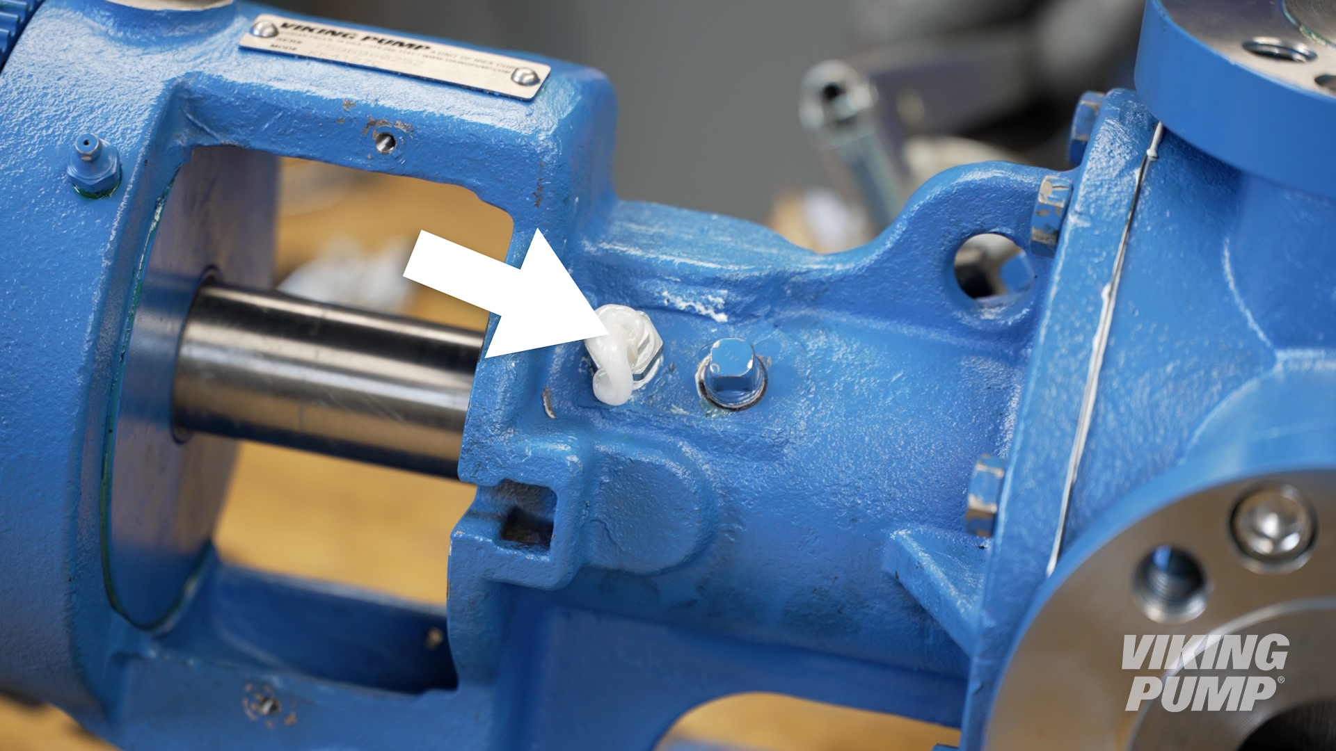 |
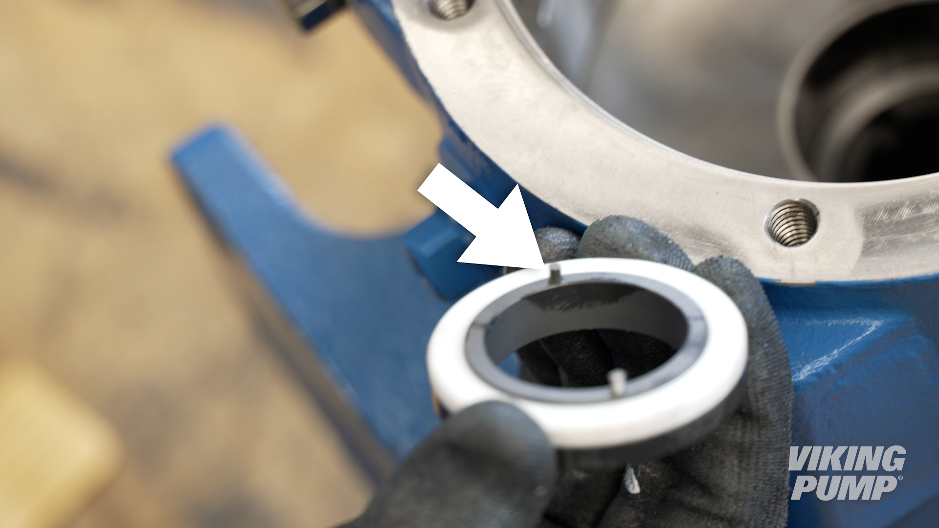
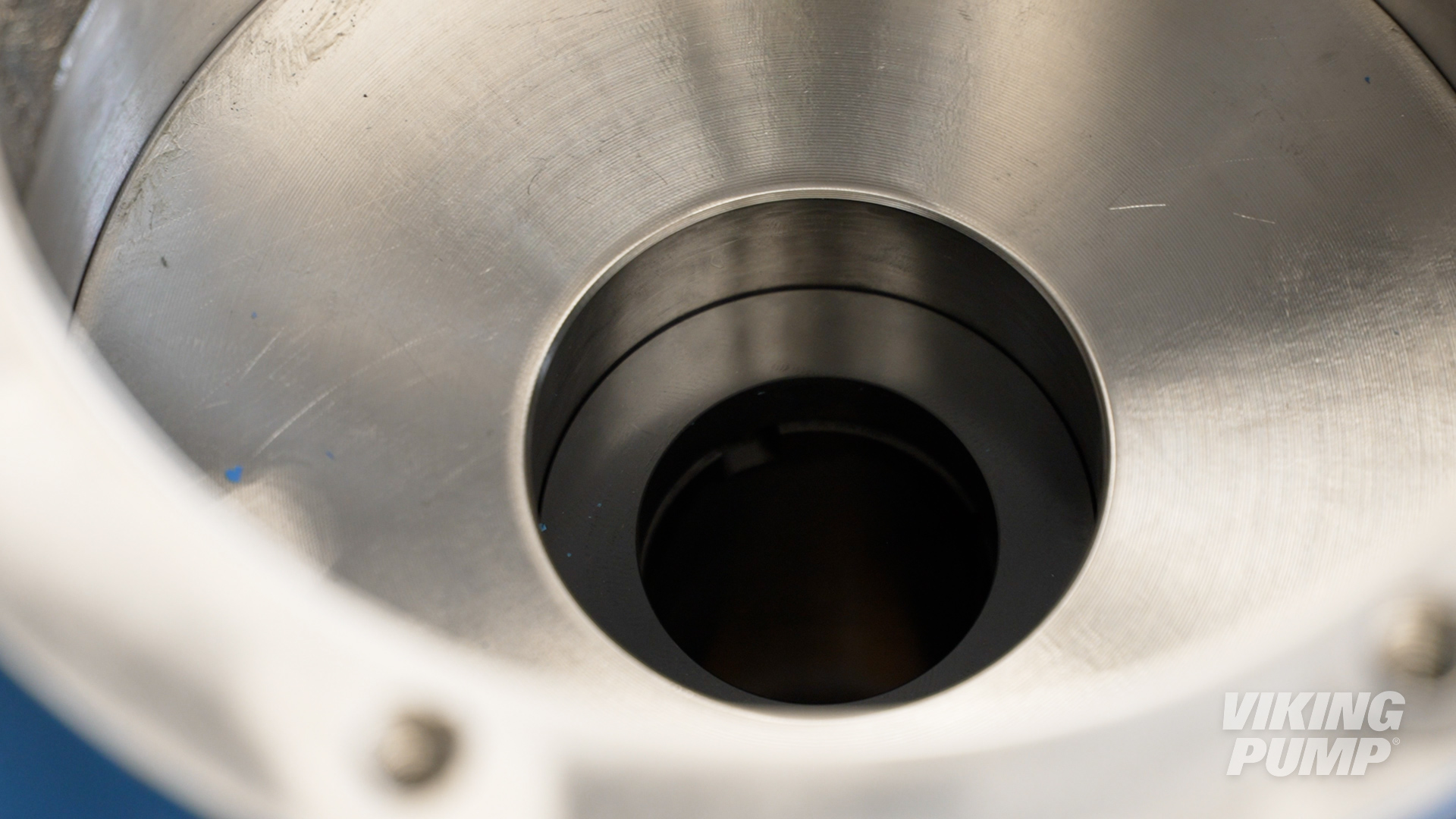
How does a behind the rotor seal work?
Behind the rotor mechanical seals work by utilizing two separate seal faces. One seal face (static) is typically installed into the pump housing, or bracket, while the other (rotary face) is installed onto the base of the pump shaft against the rotor. These two seal faces are glossy and highly finished. When liquid is being pumped, process fluid will work it’s way toward the seal faces. When liquid finally enters the space between the seal faces, a hydrodynamic film is created which creates the seal and lubricates the faces. This is the primary seal. A spring helps hold the seal faces together to maintain the primary seal.
Secondary seals are created by o-rings, bellows, or gaskets that prevent leakage past the gland or along the shaft.
What is a behind the rotor seal?
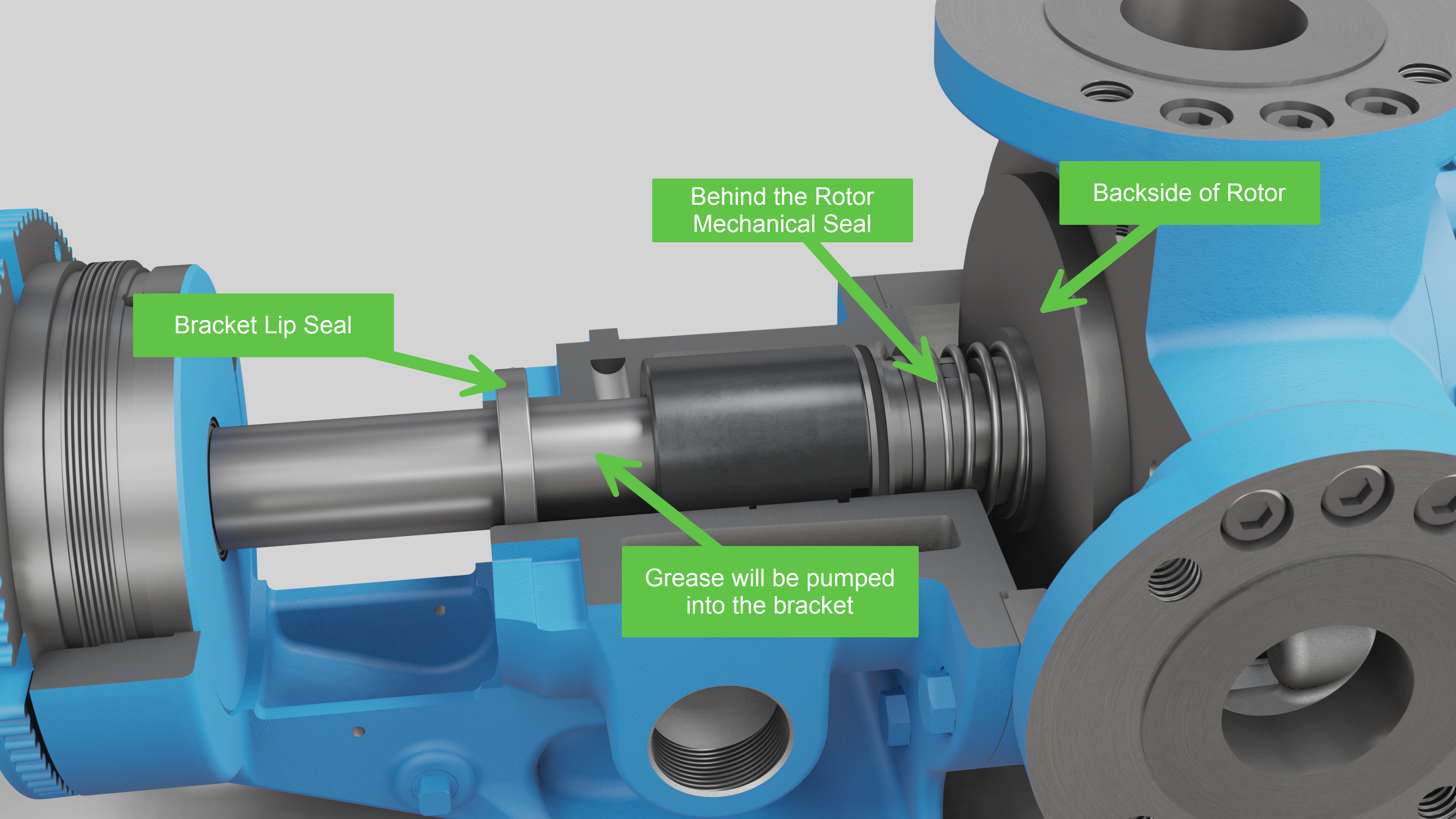
A behind the rotor seal is a type of mechanical seal that is located directly behind the rotor, isolating the shaft bushings or bearings from the pumped liquid. This type of seal is an alternative to seals that are located in the stuffing box of the pump.
Because the rotating shaft is not being lubricated by the process liquid, the bracket must be filled with an application appropriate grease. A lip seal is installed in the face of the bracket to maintain the grease barrier.
How to install a mechanical Seal
Here are some basic steps for installing a cartridge seal. These steps will vary depending on the type of seal and the pump technology it’s going into, but for this example these steps relate to installing a cartridge mechanical seal into Viking Pump’s 4124A Series™.
| 1. Place the seal installation sleeve into the shaft and lubricate the sleeve and shaft. | 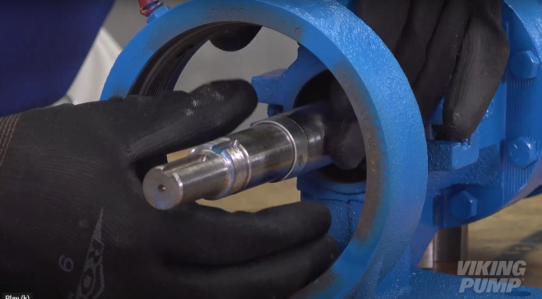 |
| 2. Slide the seal assembly onto the shaft and over the installation sleeve until the assembly contacts the bracket face. | 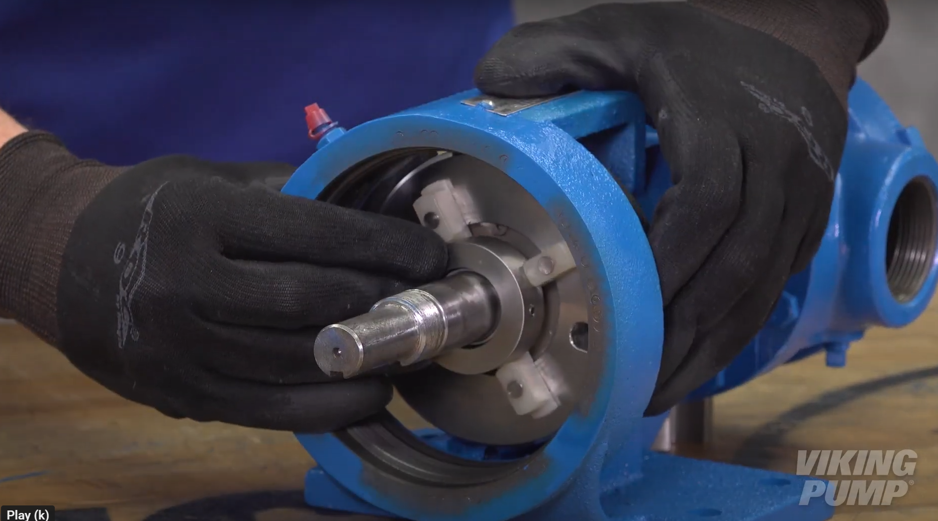 |
| 3. Remove the installation sleeve. | |
| 4. Reassemble the pump and set the end clearance. | |
| 5. Install the gland cap screws. Do not fully tighten at this time. | 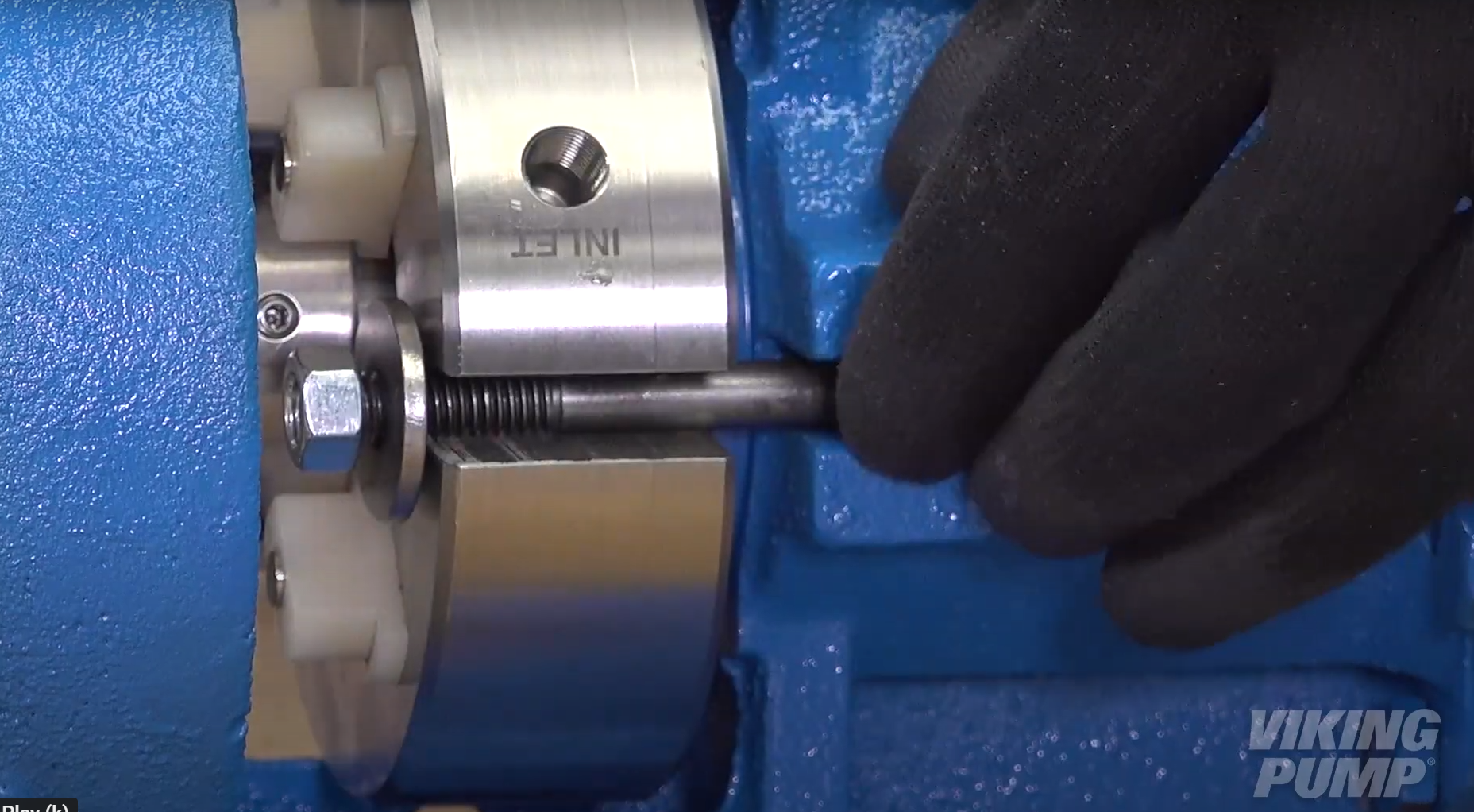 |
| 6. Turn the shaft several times to center the seal. | |
| 7. Tighten the cap screws tight enough to compress the seal gasket. | |
| 8. Evenly tighten the seal sleeve set screws to set the collar to the shaft. | 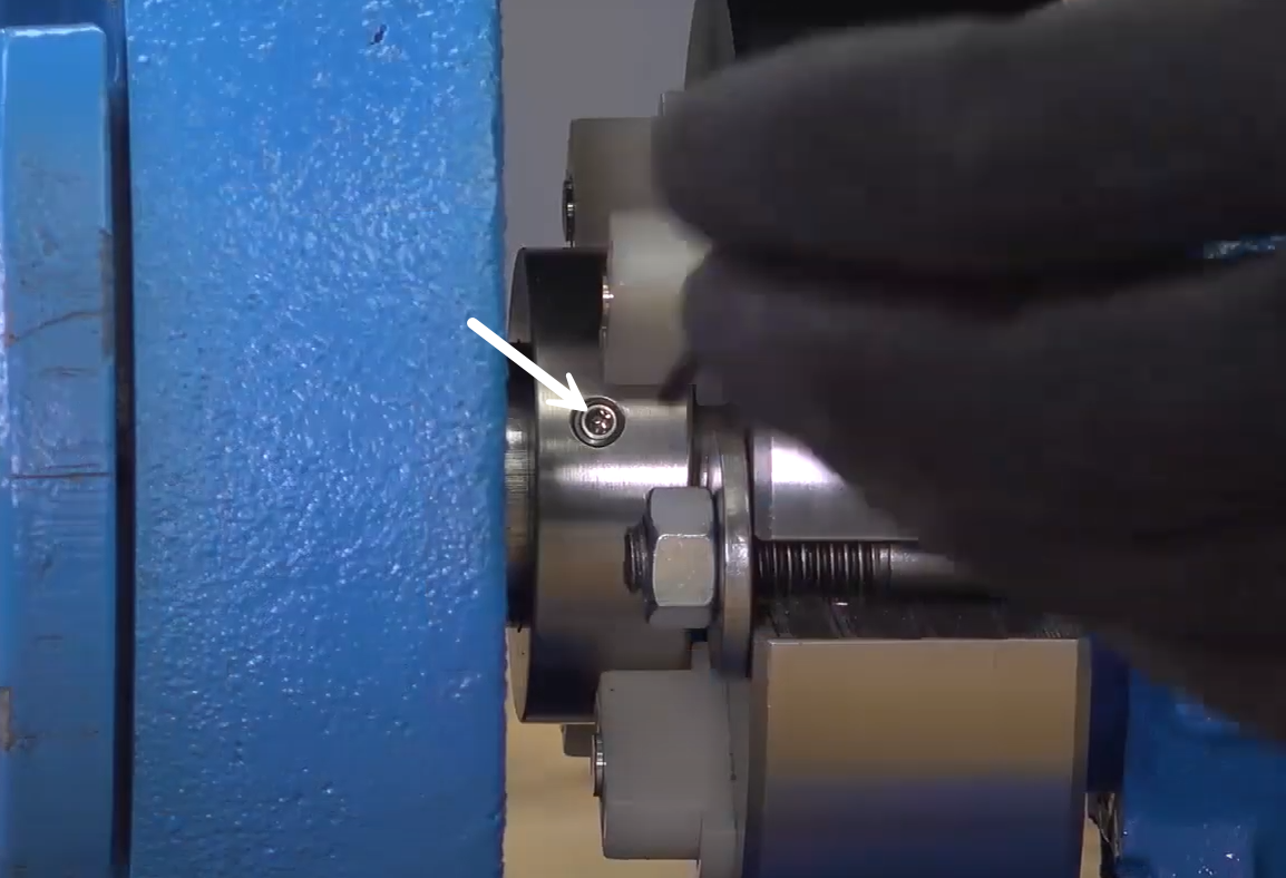 |
| 9. Rotate or remove the seal spacers and check rotation. | 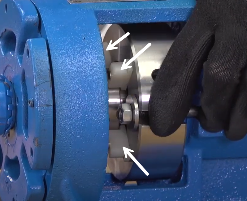 |
| 10. Reconnect seal plan or plug unused connections. | |
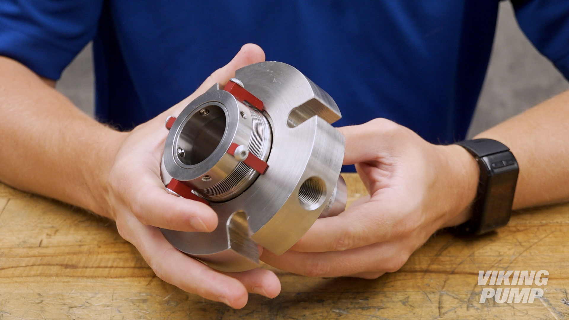
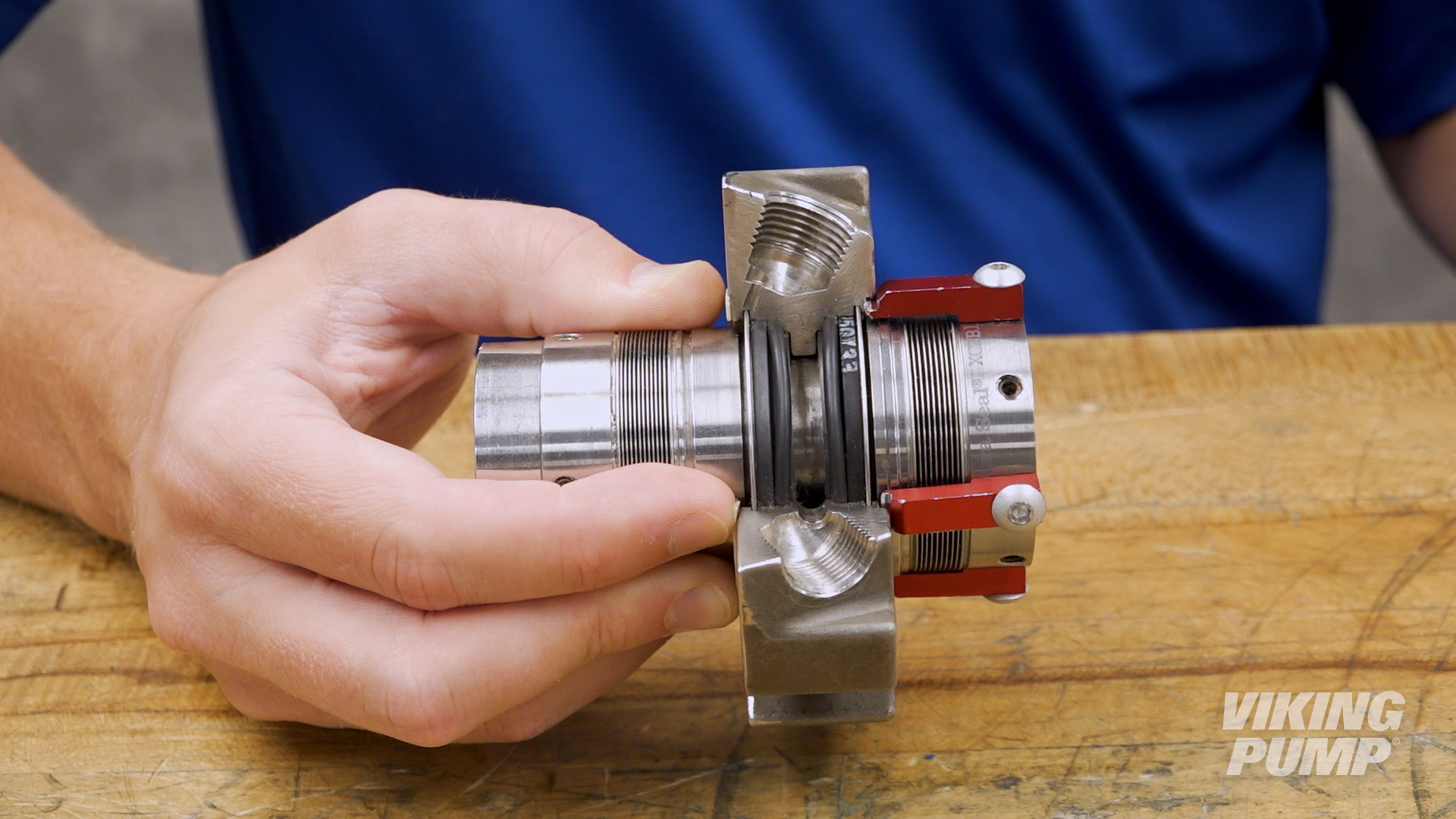
What are the different types of cartridge seals
While there are many different types of cartridge seals, here are a few examples offered by Viking Pump:
 |
 |
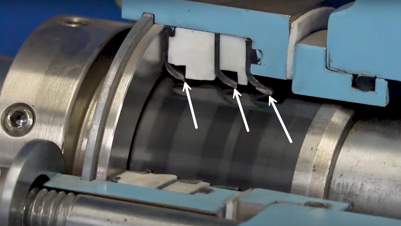 |
| Cartridge Mechanical Seal | Double Mechanical Seal | Cartridge Triple Lip Seal |
How to install an API 682 seal into a Viking pump
| 1. Install the tapered seal installation sleeve onto the shaft. Make sure the shaft is free of debris or wear that could damage the seal. | 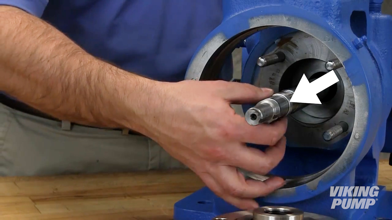 |
| 2. Lubricate the shaft, installation sleeve, and the inside of the rotor member of the seal with a generous amount of light oil. | 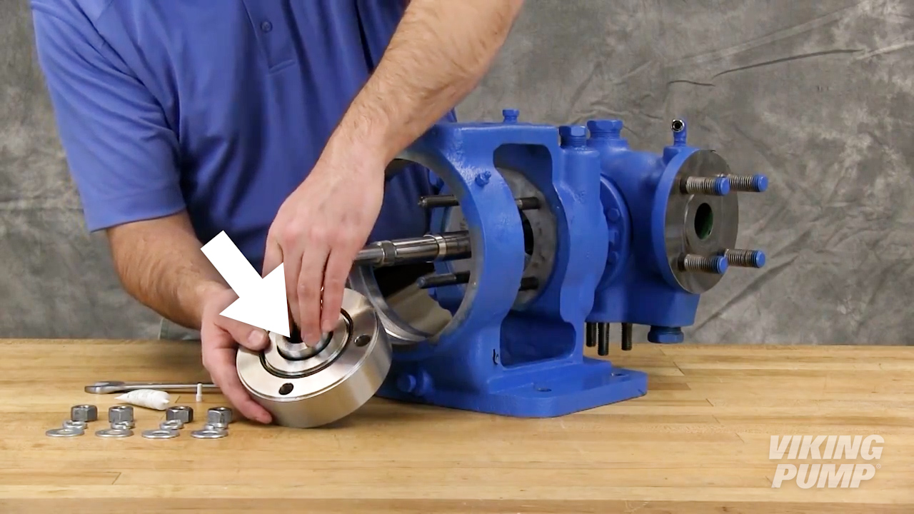 |
| 3. Install the seal onto the shaft making sure the flush port is at the 12 o’clock position. | 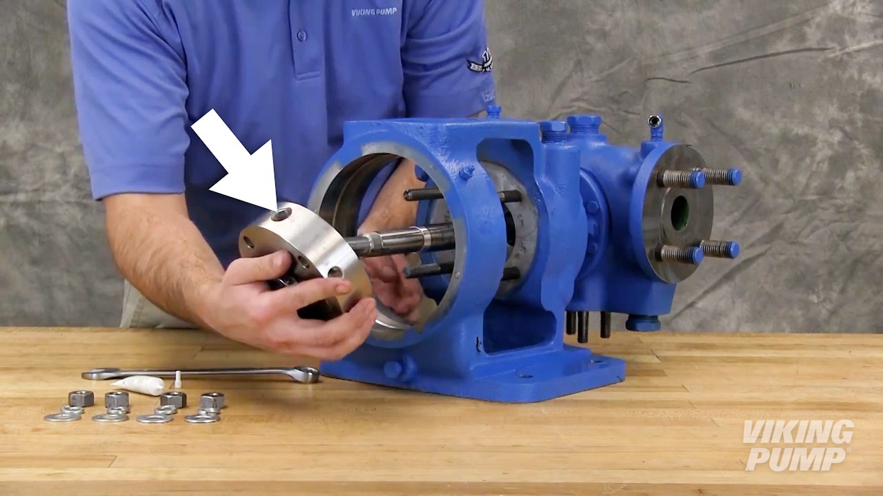 |
| 4. Secure the seal gland to the bracket face using the proper hardware. | 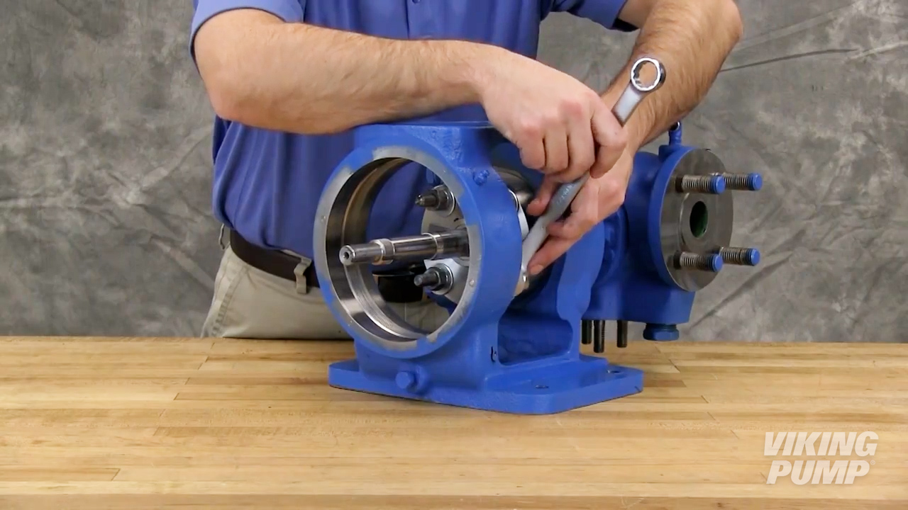 |
| Complete the rest of the pump assembly. Once end clearance for the pump is set you may proceed to final seal installation steps. | |
| 5. Once end clearance is set, tighten the set screws on the cartridge seal drive collar | 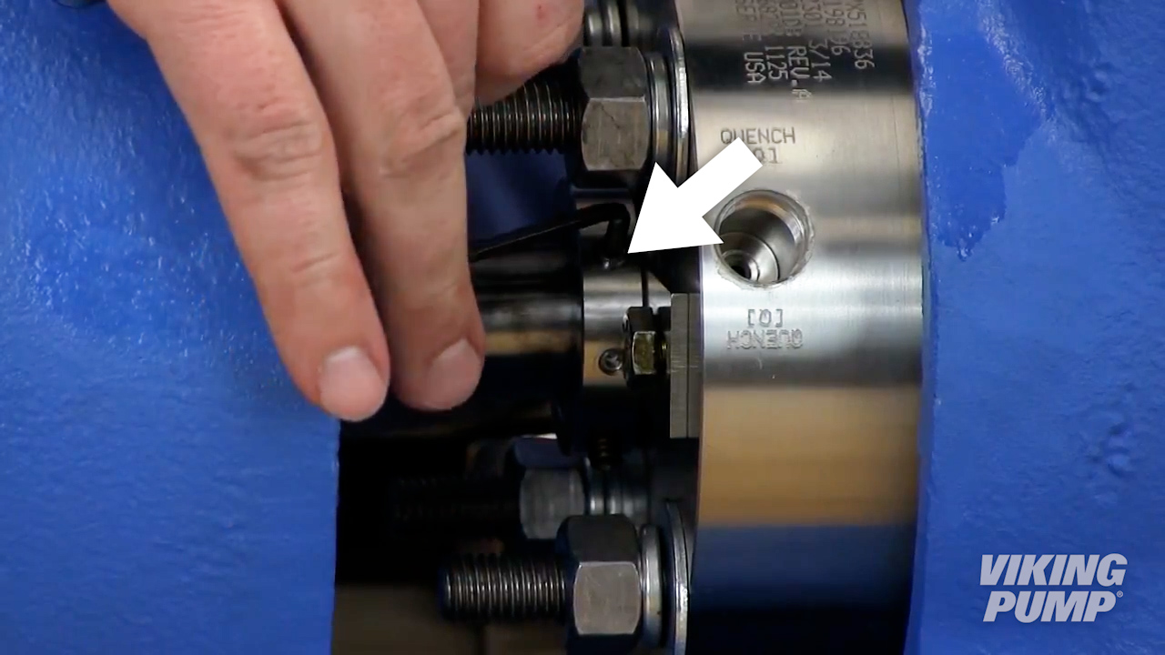 |
| 6. Remove or turn the centering clips to clear the seal drive collar. | 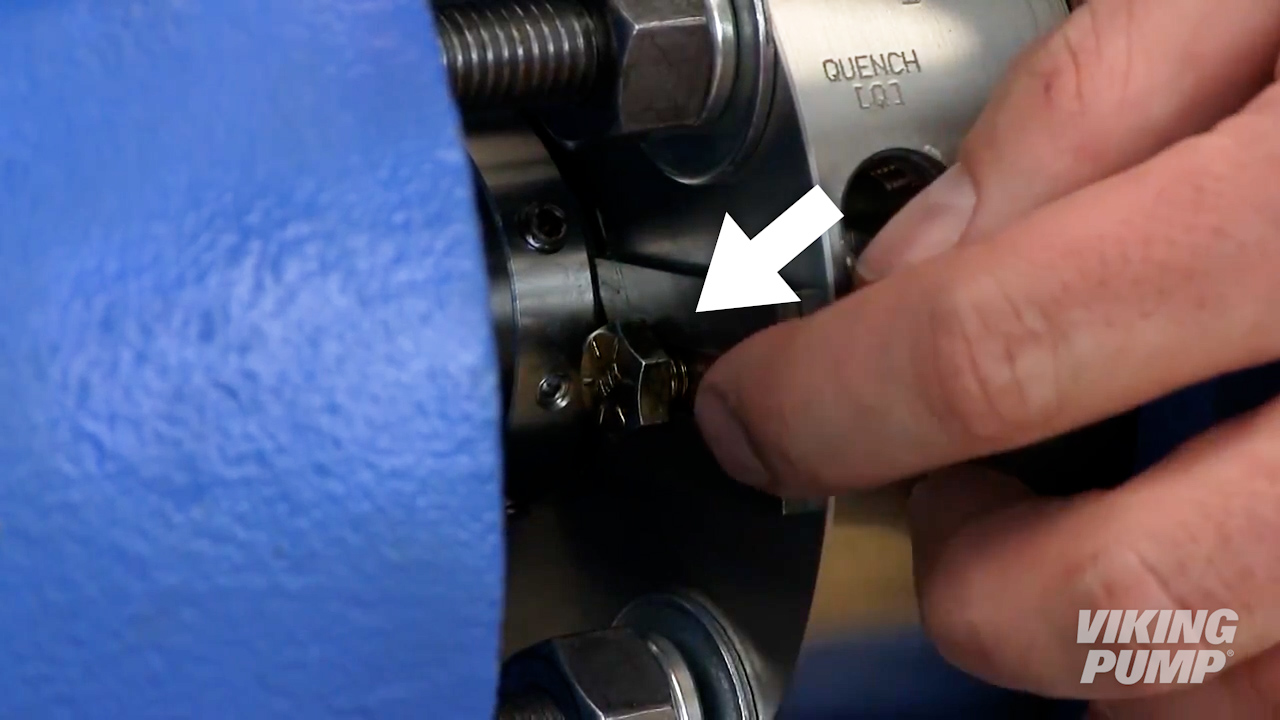 |
| 7. Ensure the pump turns freely. | 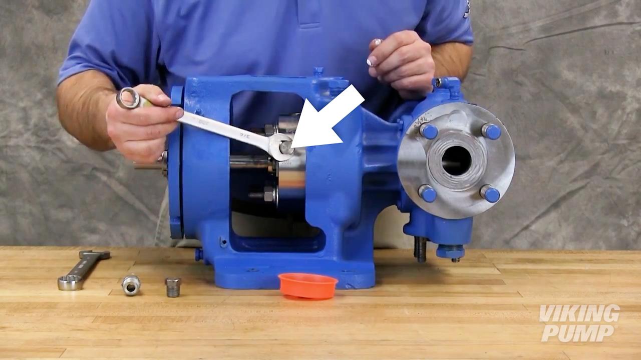 |
| 8. Install seal plugs or piping plan, using the appropriate sealing compound, into the seal gland. | 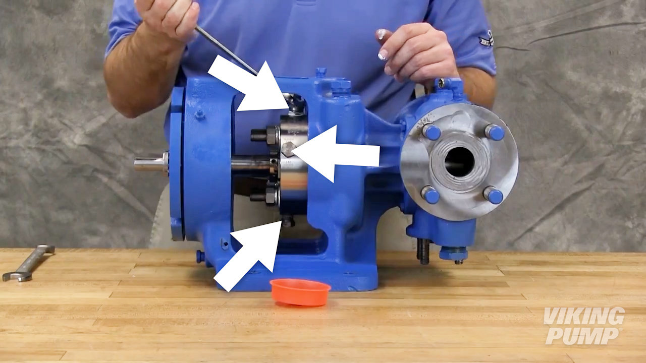 |
| 9. Install guards and barrier fluid lines as needed. | 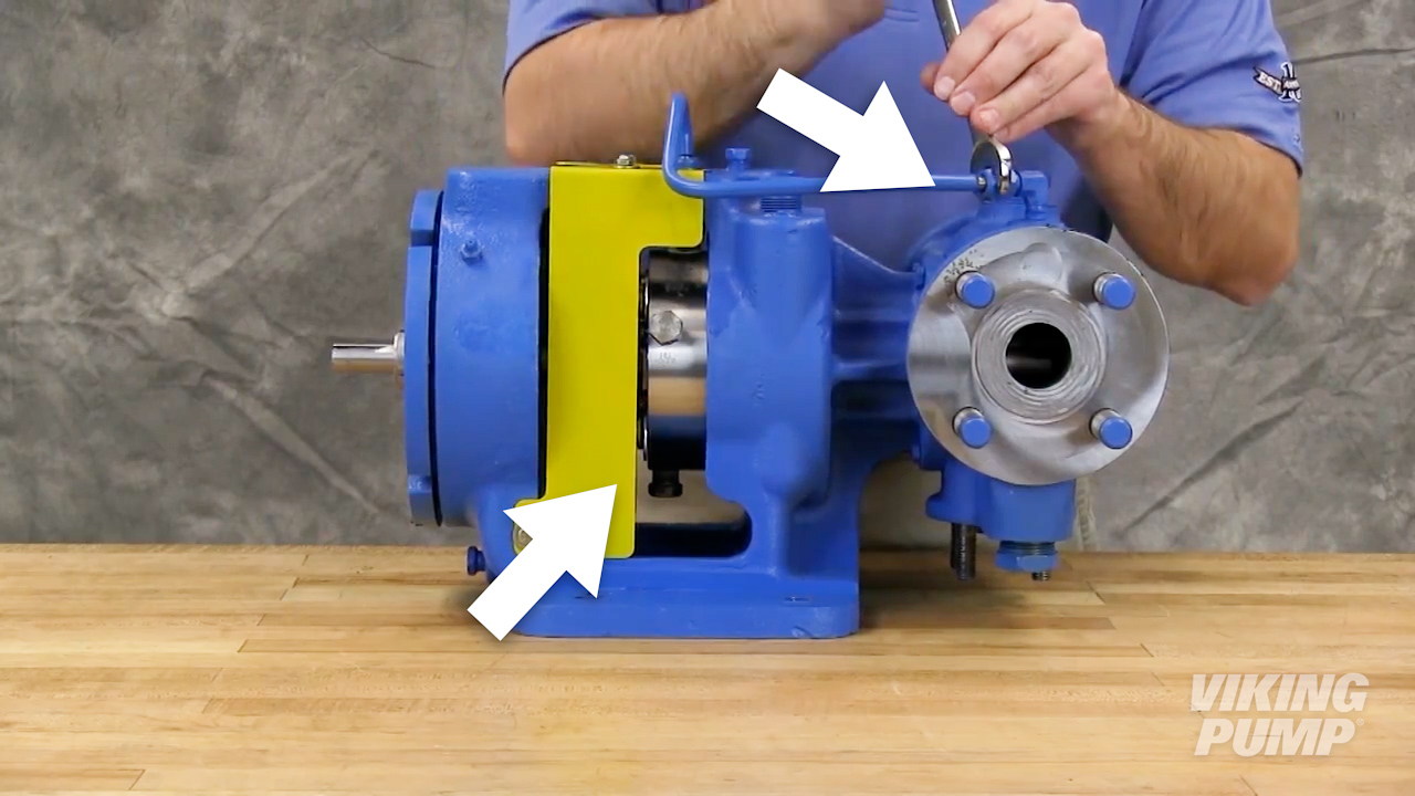 |
What is an API 682 seal?
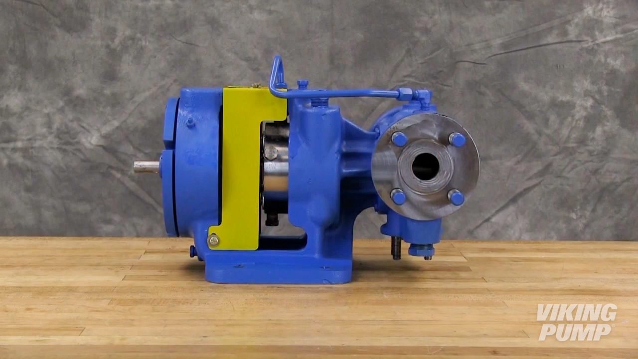
An API 682 seal is a special cartridge mechanical seal which has been designed and tested to the American Petroleum Institute’s API 682 standard.
What is API 682?
API 682 is the standard used for mechanical seals (or other sealing solutions) used in centrifugal and rotary pumps that are to be applied in petroleum, natural gas and chemical industries. The purpose of the standard is to show compliance in hazardous applications where more reliable seals are required.
What is the difference between a cartridge seal and a component seal?
Component seals are many individual pieces, installed separately, that work together to create a seal. Cartridge seals are self-contained – housing each component in a preassembled unit.
What is a cartridge seal?
A cartridge seal is a mechanical seal or lip seal(s) that is contained in a preassembled housing to aid in the seal’s installation, maintenance, and replacement.
Viscosity
How do you measure viscosity in Sabolt Seconds Universal (SSU)?
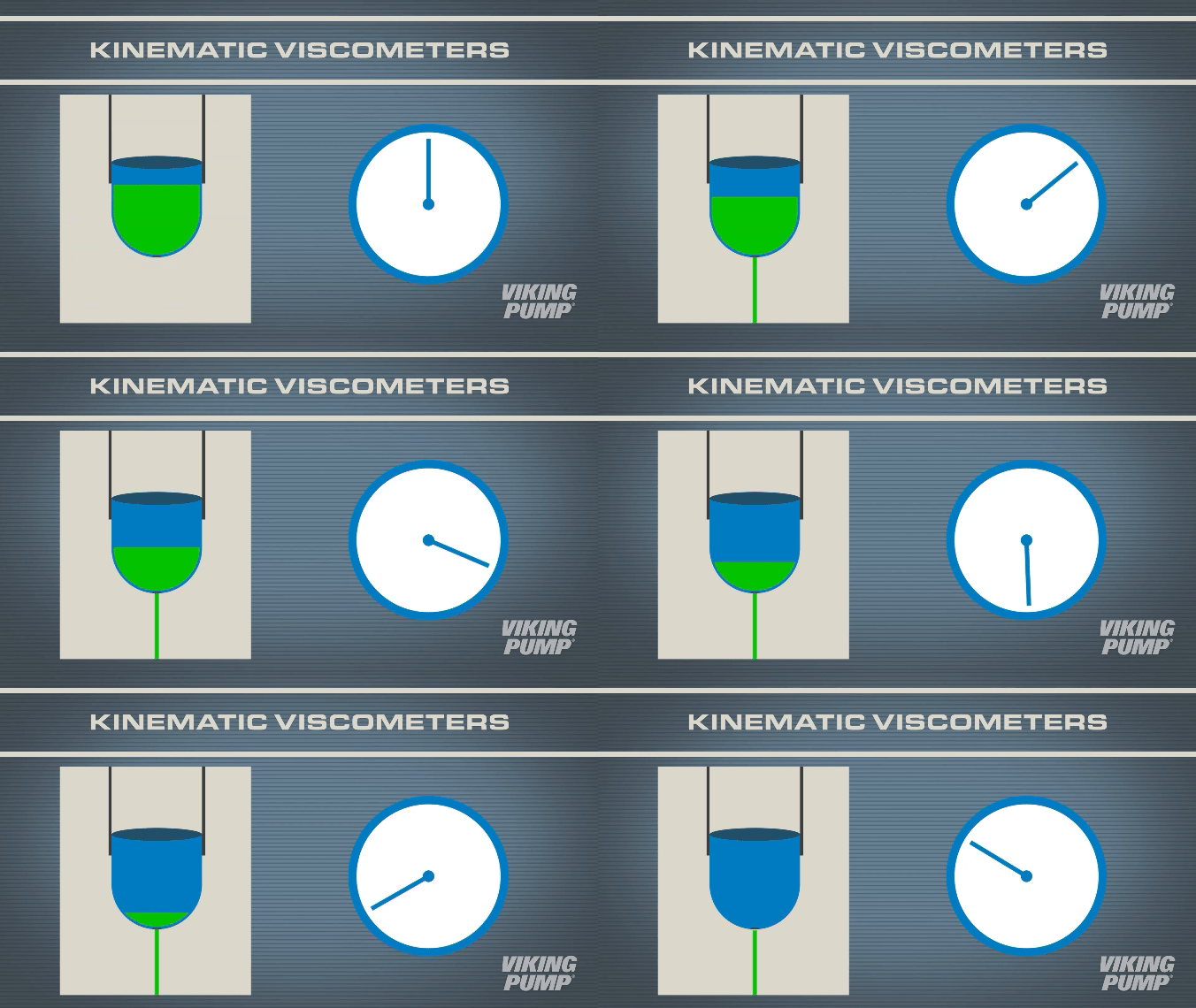
For thin liquids like water, oil, or paint - kinematic viscometers can be used. The simplest versions feature a cup with an orifice at the bottom. The cup is filled and then a time measurement is taken.
What are Sabolt Seconds Universal?
Sabolt Seconds Universal (SSU), otherwise known as Saybolt Universal Seconds (SUS) is a unit of viscosity measurement. This value refers to the amount of time (in seconds) it takes and a measured quantity of liquid to drain from a kinematic viscometer.
How do you measure millipascal seconds?
For thin liquids like water, oil, or paint kinematic viscometers can be used. The simplest versions feature a cup with an orifice at the bottom. The cup is filled and then a time measurement is taken.
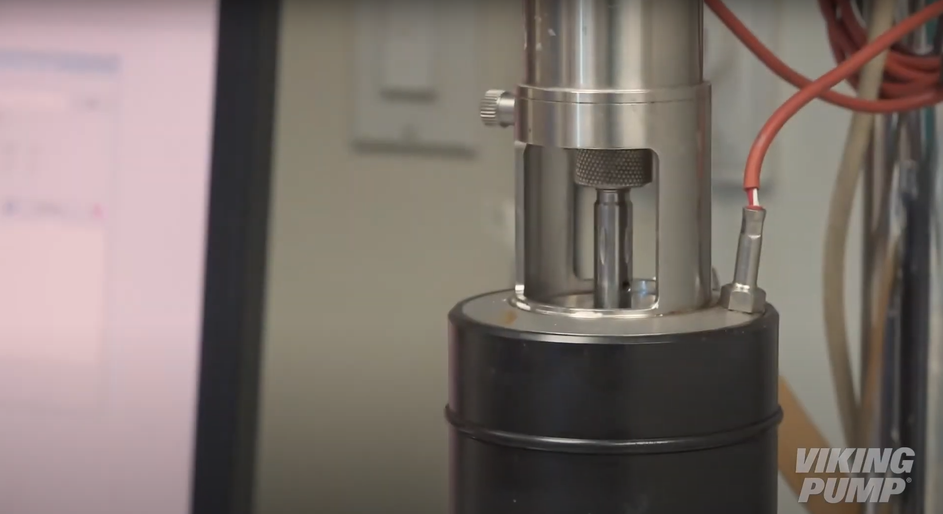
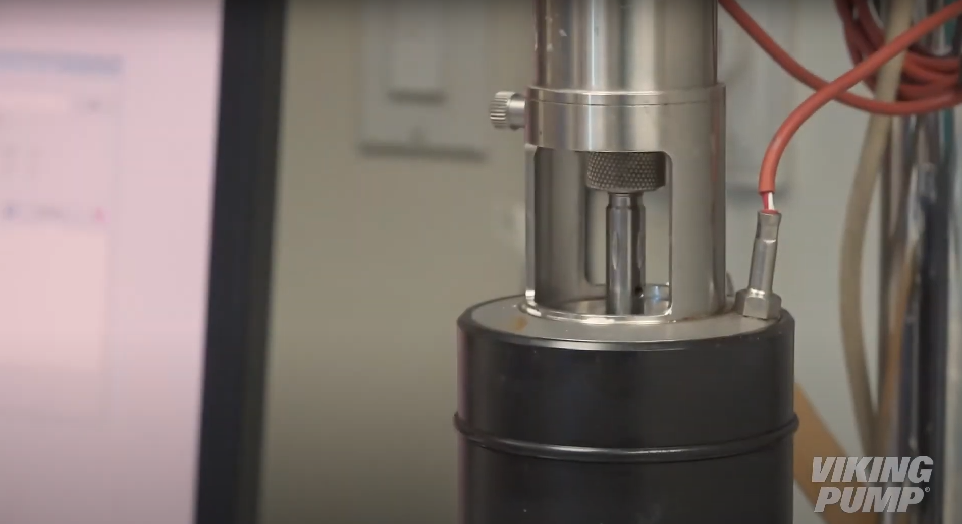
For thicker liquids, a dynamic viscometer can be used. This type of viscometer uses a rotating spindle submerged in sample liquid. This measures the shear stresses as the liquid creates viscous drag. This has the added benefit of measuring a liquid's shear sensitivity.
What is a millipascal second (mPas)?
A millipascal second (mPas) is a unit of viscosity measurement equivalent to 1 centipoise.
How do you measure liquids in millimeter squared per second?
For thin liquids like water, oil, or paint kinematic viscometers can be used. The simplest versions feature a cup with an orifice at the bottom. The cup is filled and then a time measurement is taken.
For thicker liquids, a dynamic viscometer can be used. This type of viscometer uses a rotating spindle submerged in sample liquid. This measures the shear stresses as the liquid creates viscous drag. This has the added benefit of measuring a liquid's shear sensitivity.
What is a millimeter squared per second (mm2/s)?
A millimeter squared per second is a unit of viscosity measurement equivalent to 1 centistoke.
What are Low Viscosity Pumps used for?
Since Low Viscosity Pumps have vanes that run in contact with the casing wall, they are commonly used in thin liquid applications like solvents, alcohols, and various acids or bases.
How does a Low Viscosity Pump work?
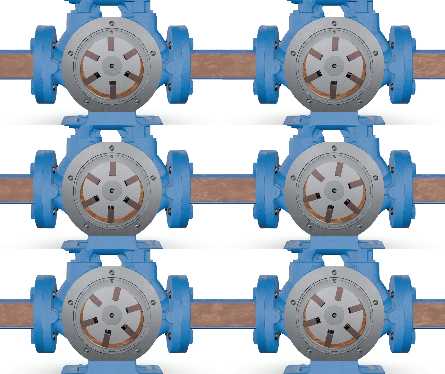
Low Viscosity Pumps, or vane pumps move fluid using the rotary motion of multiple sliding vanes. Vane pumps consist of a slotted rotor rotating inside a cam shaped housing. This rotor is located close to the wall of the cam so that a crescent-shaped cavity is formed on the opposite wall.
Each rotor slot contains a sliding vane. As the rotor rotates, centrifugal force, hydraulic pressure, and push rods work together to extend each vane to the casing wall. This creates an expanding cavity on the inlet side – creating a vacuum which pulls liquid into the pump. Liquid is trapped between the vanes and the casing wall. The rotor rotation moves the liquid cavities around to the outlet side of the pump.
At the outlet side, the vanes are forced back into their slots, decreasing the cavity size and forcing the liquid through the outlet port.
What is a Low Viscosity Pump?
A Low Viscosity Pump is a series of Viking Pump vane pump named for their ability to handle low viscosity liquids at high pressures.
What are Krebs Units?
Krebs Units (KU) are a measure of viscosity primarily used in the paints and coatings industry. Krebs Units are measured using a Stormer viscometer. A Stormer viscometer utilizes a paddle spindle submerged in the liquid sample. One Krebs Unit is equivalent to the weight in grams required to turn that submerged spindle 100 times in 30 seconds.
How do you measure centistokes?
For thin liquids like water, oil, or paint kinematic viscometers can be used. The simplest versions feature a cup with an orifice at the bottom. The cup is filled and then a time measurement is taken.
For thicker liquids, a dynamic viscometer can be used. This type of viscometer uses a rotating spindle submerged in sample liquid. This measures the shear stresses as the liquid creates viscous drag. This has the added benefit of measuring a liquid's shear sensitivity.
What is a centistoke?
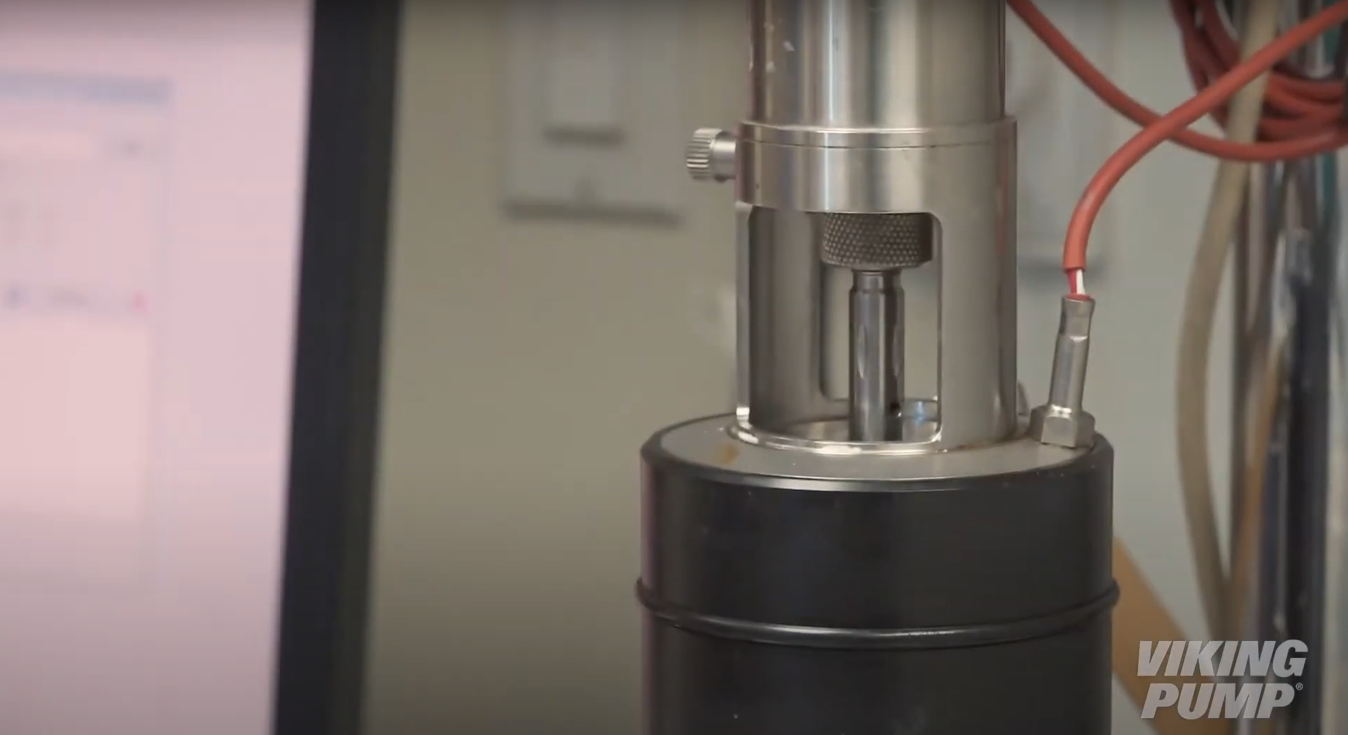
A unit of viscosity measurement equivalent to 1 millimeter squared per second. This value quantifies a liquid’s rate of flow under the influence of gravity.
Are centipoise and centistokes the same thing?
No, not exactly. Centipoise (cP) measures a fluid’s internal resistance to flow – in other words, how thick is the liquid.
Centistokes measures a liquid’s kinematic viscosity which is the ratio of the resistance to flow and density. Basically, how fast does the liquid move under the influence of gravity.
How do you measure centipoise?
For thin liquids like water, oil, or paint kinematic viscometers can be used. The simplest versions feature a cup with an orifice at the bottom. The cup is filled and then a time measurement is taken.
For thicker liquids, a dynamic viscometer can be used. This type of viscometer uses a rotating spindle submerged in sample liquid. This measures the shear stresses as the liquid creates viscous drag. This has the added benefit of measuring a liquid's shear sensitivity.
What does centipoise mean?
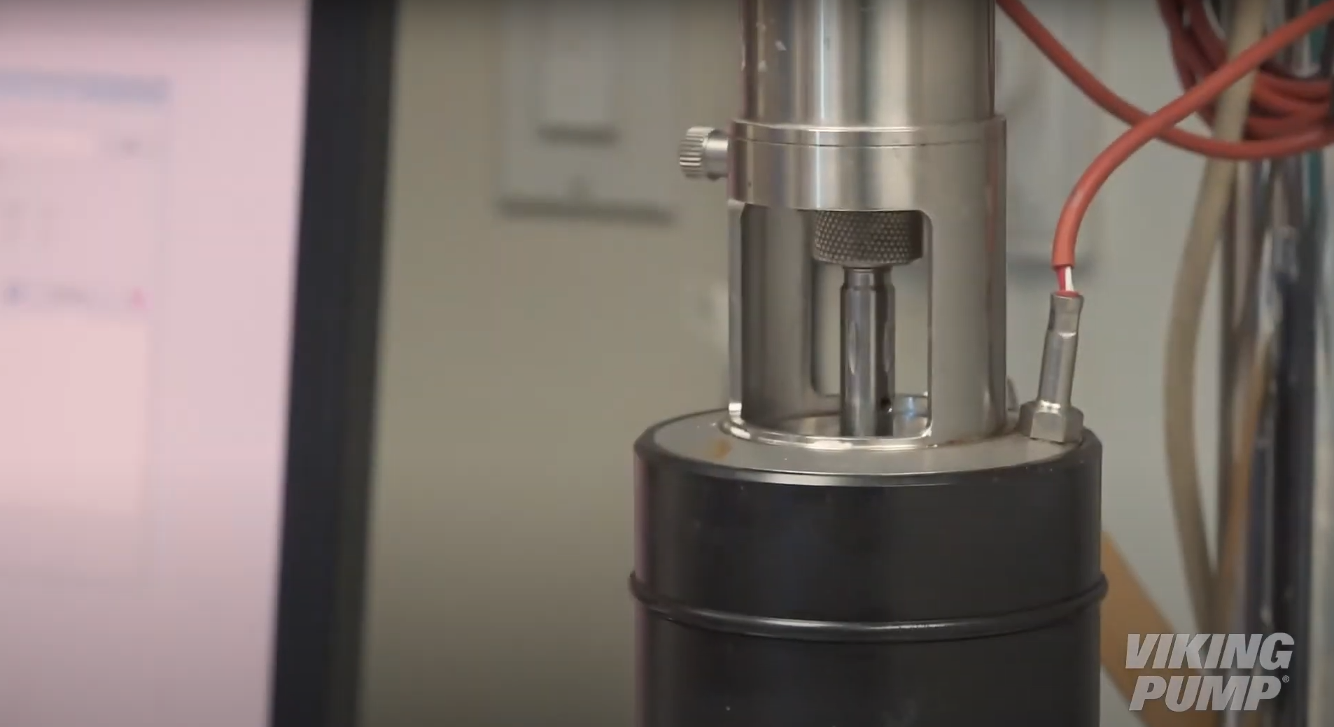
A unit of viscosity measurement equivalent to 1 millipascal-second. This value quantifies a liquid’s resistance to flow.